Inspection system and method

a technology of inspection system and inspection method, applied in the field of inspection of areas, can solve problems such as blurry target images, and achieve the effects of improving inspection system performance, improving inspection of lateral pipes, and extending imaging rang

Inactive Publication Date: 2011-11-08
ENVIROSIGHT
View PDF32 Cites 13 Cited by
  • Summary
  • Abstract
  • Description
  • Claims
  • Application Information

AI Technical Summary

Benefits of technology

[0010]The present invention provides a system and method for improving inspection of lateral pipes by enabling the imaging head to focus on a target at longer range down a pipe than previously possible. In one respect, Applicants recognize that the performance of the inspection system can be improved dramatically if the imaging head is positioned reliably in an optimum location with respect to the lateral pipe. This position is referred to herein as the “sweet spot.” Generally, the optimum position is where the illumination source or lamp is positioned such that its light beam propagates down the pipe to the furthest extent possible before reflecting off the pipe wall and diffusing. Since a target must be well illuminated for effective imaging, the further light is able to propagate down the pipe, the greater the imaging range will be. If the pipe is essentially free of material, the sweet spot will be approximately in the center of the pipe. If, however, the pipe is partially filled with material, particularly liquids, which tend to reflect light, then the sweet spot will be approximately in the center point of the space above the material.

Problems solved by technology

That is, if the vertical position of the imaging head is above or below the sweet spot initially, tilting the head will not rectify the situation, but rather cause the light beam to be angled relative to the pipe.
Imaging at relatively long range using high magnification requires the head to remain very still, otherwise the target images will be blurry.

Method used


Image

  • Inspection system and method
  • Inspection system and method
  • Inspection system and method

Examples


Embodiment Construction

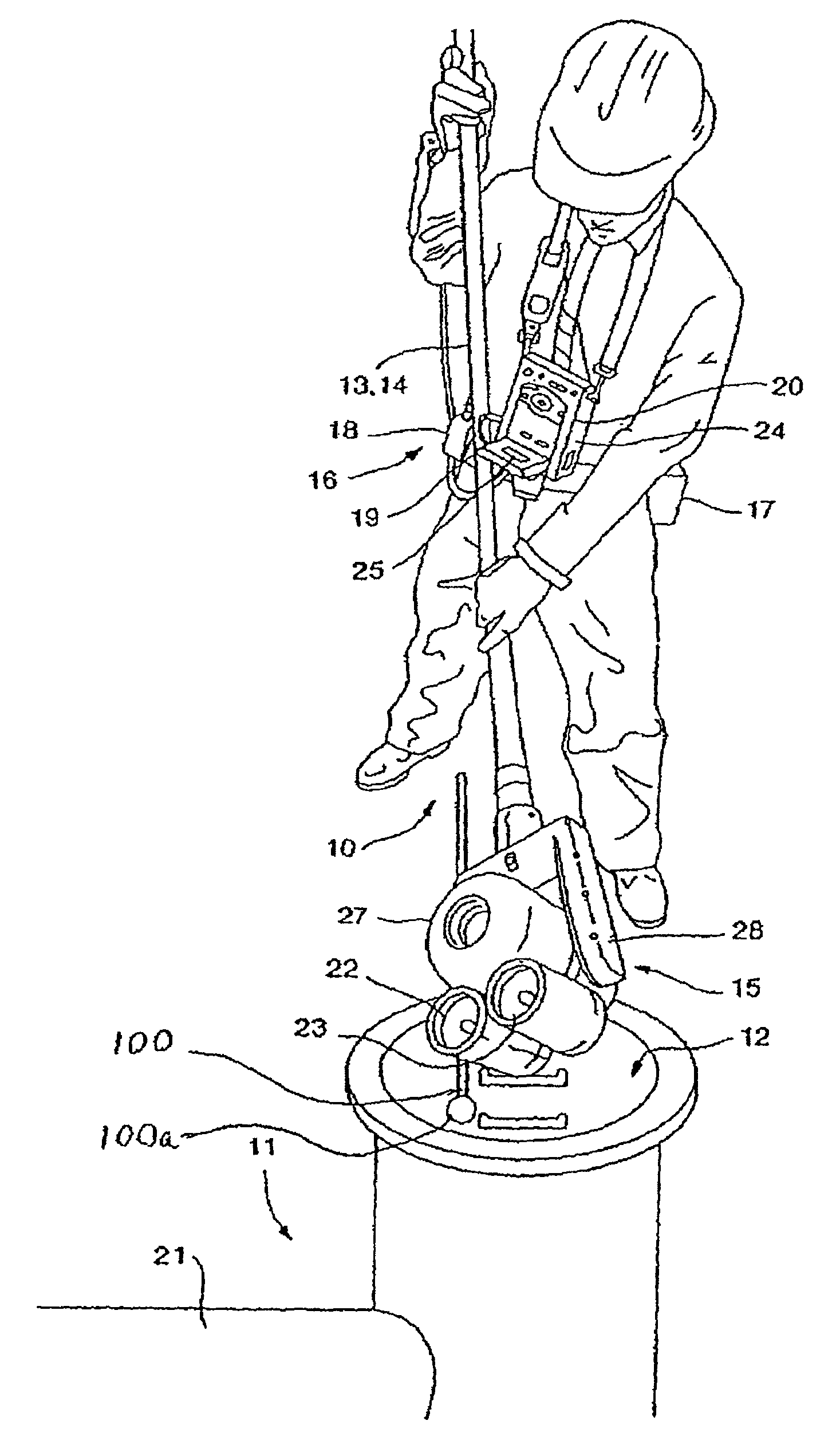
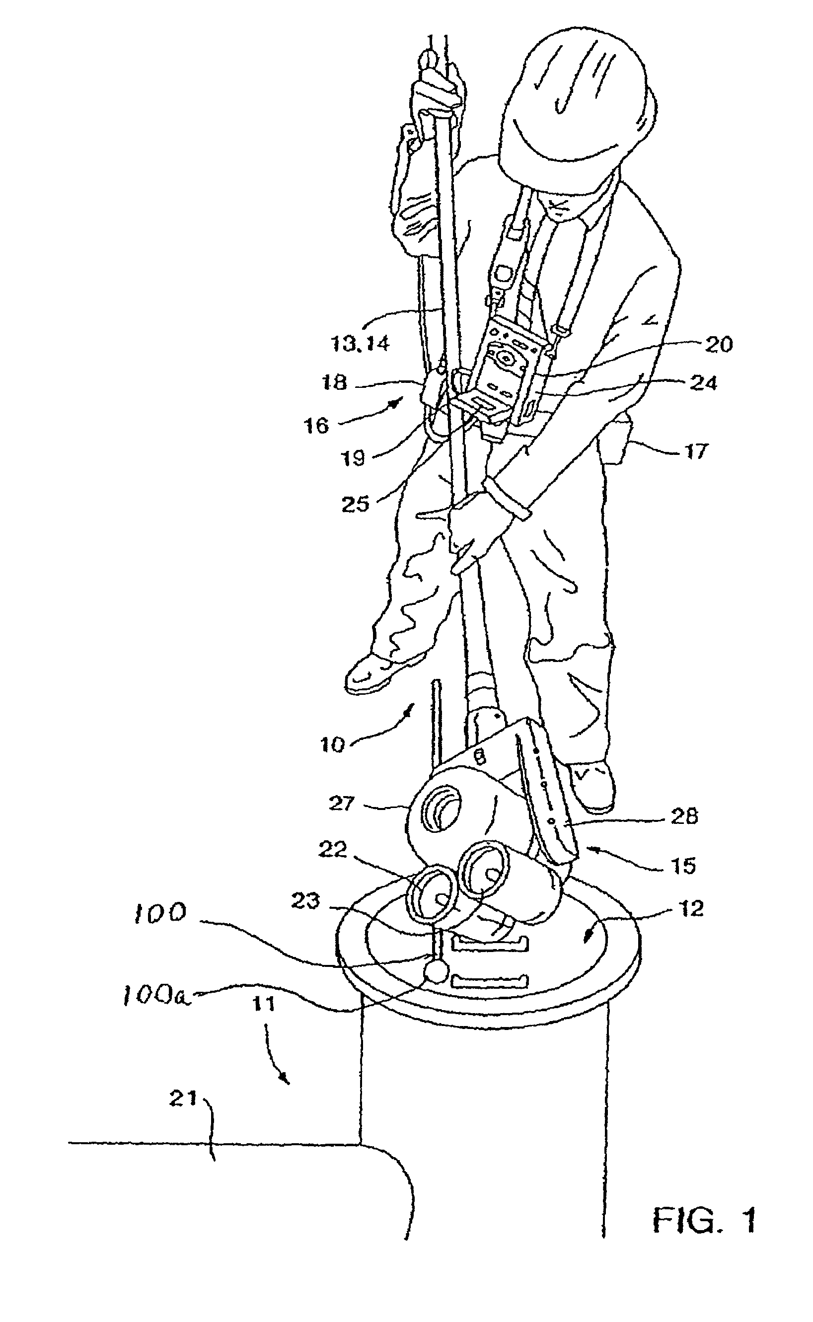
[0036]Referring to the drawings, FIG. 1 shows a user operating one embodiment of the inspection system 10 to ascertain whether an invasive procedure is warranted. Using the system 10 comprises the steps of (a) extending an imaging head 15 into the manhole 12 using a positioning system 13, the imaging head 15 comprising an imaging device (within enclosure 27) and at least one lamp 23 capable of producing a light beam (not shown), the positioning system comprising an elongated member 14 and a targeting fixture 100 operatively connected thereto, the imaging head 15 being attached to one end of the elongated member 14, the targeting fixture 100 having a distal end 100a biased outwardly from the imaging head 15; (b) placing the distal end 100a on a rigid surface proximate to the lateral pipe 21; (c) pushing down on the elongated member 14 such that the distal end 100a resiliently moves toward the imaging head 15, thereby allowing the light beam to be centered approximately in the lateral...


PUM

PropertyMeasurementUnit
focal lengthaaaaaaaaaa
diameteraaaaaaaaaa

Abstract

A method of inspecting a lateral pipe extending from a manhole, said method comprising: (a) inserting an imaging head into said manhole using a positioning system, said imaging head connected to an elongated member and comprising an imaging device adapted to convert an image to an image signal, a lens optically coupled to said imaging device, and at least one lamp suitable for projecting a light beam, said lamp having a beam that is adjustable to enable said beam to move relative said imaging device; (b) imaging a target located within said lateral pipe; (c) holding said imaging device essentially steady while imaging said target and adjusting said beam to adjust the illumination of said target.

Description

REFERENCE TO RELATED APPLICATIONS[0001]This application claims priority to U.S. Provisional Patent Application No. 60 / 726,918 filed Oct. 14, 2005, U.S. application Ser. No. 11 / 368,902, now U.S. Pat. No. 7,480,041, and all of which are hereby incorporated by reference.FIELD OF INVENTION[0002]The present invention relates generally to the inspection of areas that are hard-to-reach, inaccessible or uninhabitable for humans. More specifically, the invention relates to the inspection of manholes and lateral pipes radiating therefrom prior to invasive procedures such as cleaning and comprehensive exploratory inspections.BACKGROUND OF THE INVENTION[0003]It is often necessary to inspect and maintain areas under conditions that render them inaccessible or otherwise uninhabitable for humans for an extended period. These conditions include, for example, small confined spaces and harsh environments such as insufficient air / oxygen, presence of toxins, radioactivity, contamination, excessive dust...

Claims


Application Information

Patent Timeline
Patent Type & Authority Patents(United States)
IPC IPC(8): G01N21/00
CPCG01N21/94G01N21/954G02B23/2407G01N2201/021G01N2021/9544
Inventor LINDNER, RICHARD
Owner ENVIROSIGHT
Why Eureka
Try Eureka