String securing device

a securing device and string technology, applied in the direction of fastenings, press-button fasteners, footwear, etc., can solve the problems of uneven biasing force to the arms, time-consuming and labor-intensive installation of springs b>622/b> into the reception holes, etc., and achieve the effect of simple structure and smooth operation of the cap

Active Publication Date: 2012-08-21
CHEN CHIN CHU
View PDF24 Cites 118 Cited by
  • Summary
  • Abstract
  • Description
  • Claims
  • Application Information

AI Technical Summary

Benefits of technology

[0008]The primary object of the present invention is to provide a string securing device which includes simple structure and the cap is operated smoothly.

Problems solved by technology

Besides, the installation of the springs 622 into the reception holes requires time.
This may result in uneven biasing forces to the arms 732 and may have the same problem as the first conventional securing device.

Method used


Image

  • String securing device
  • String securing device
  • String securing device

Examples


Embodiment Construction

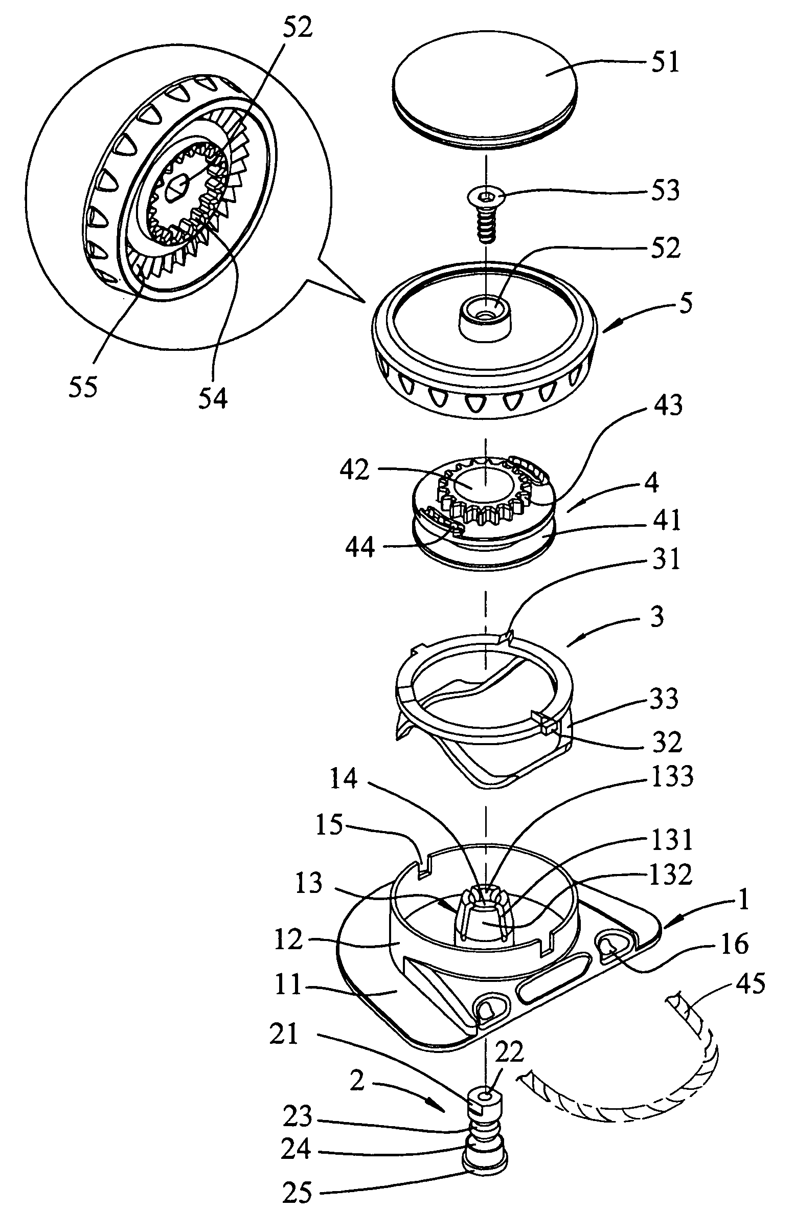
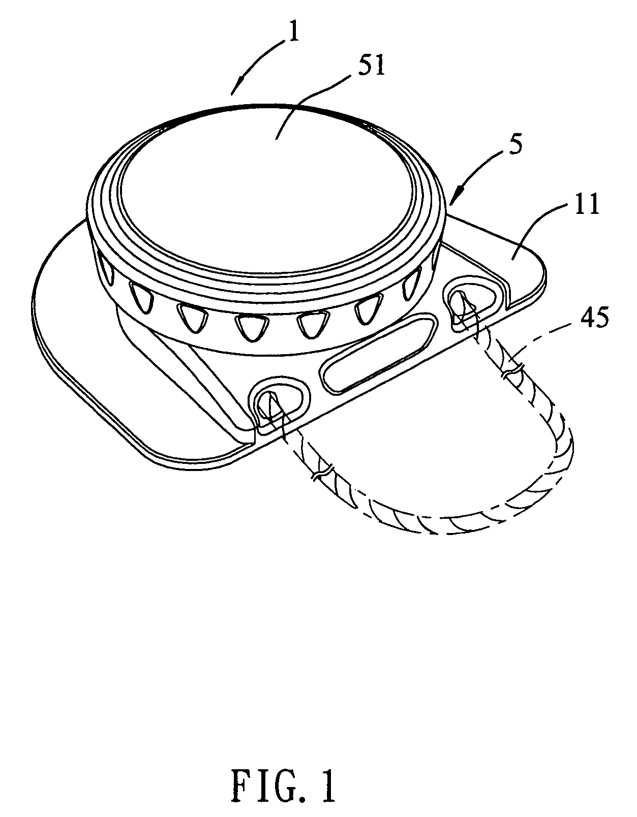
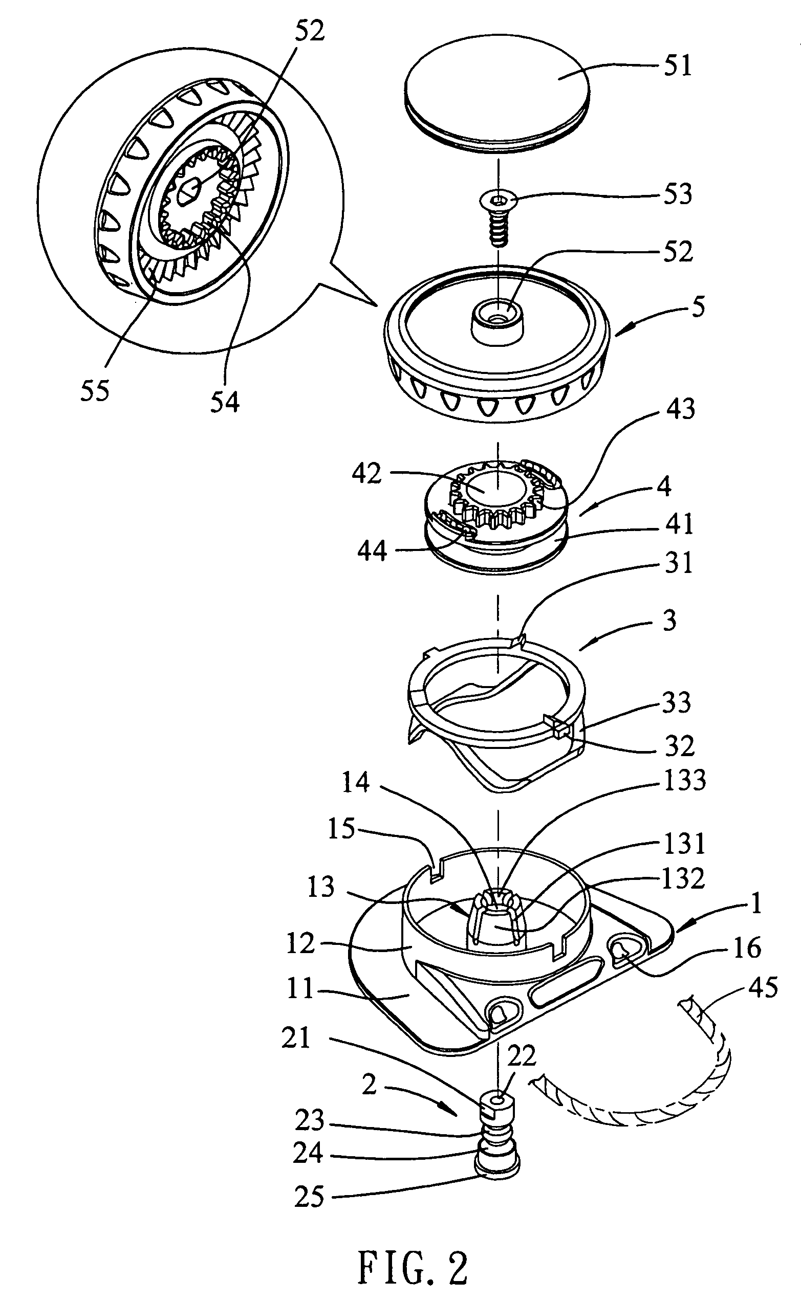
[0025]Referring to FIGS. 1 to 5, the string securing device of the present invention comprises a base 1 having a connection plate 11 so as to be fixed to an object such as a bag, helmet or shoe (not shown) and a skirt 12 extends from a top of the connection plate 11. The skirt 12 defines a space and a central post 13 extends centrally from an inner end of the space. A passage 14 is defined axially through the central post 13. The central post 13 includes multiple plates 132 and multiple axial slits 131 are located between the plates 132. Each plate 132 has a lip 133 extending inward from a top thereof and a stepped shoulder 134 is defined in an inner periphery of the passage 14. The skirt 12 includes two notches 15 defined in a top thereof and two holes 16 are defined in the base 1 so that the string 45 or shoelace extends into the holes 16.

[0026]A shaft 2 extends through the passage 14 of the central post 13 and a connection end 21 is located on a top end of the shaft 2. A first gr...


PUM


Abstract

A string securing device includes a base having a central post extending centrally therefrom. A shaft extends through the passage in the central post so as to be connected to the cap mounted to the base by a bolt which extends through the cap from a top of the cap. A ring and a spool are located between the base and the cap, wherein the spool is rotated with the cap by engagement of first and second teeth on the spool and the cap respectively. The ring has multiple ratchet teeth which are removably engaged with third teeth on the cap so as to allow the cap to rotate in one direction. The ring includes flexible members which are deformed to lower the ring and provides straight and upward force to the cap.

Description

FIELD OF THE INVENTION[0001]The present invention relates to a securing device, and more particularly, to a string securing device that is operated smoothly.BACKGROUND OF THE INVENTION[0002]A conventional string / shoelace securing device is shown in FIGS. 10 to 13, and generally includes a base 61, two positioning pins 62, a spool 63, a ring 64, a cap 65 and a wire or shoelace. The base 61 includes a connection plate 611 which is fixed to a shoe (not shown) and the spool 63 is rotatably mounted to the central post on the base 61. A bolt 612 extends through the central post from the underside of the base 61 and is connected to the post 653 on the underside of the cap 65. The two positioning pins 62 are cooperated with two springs 622 and inserted into reception holes in the base 61 and each positioning pin 62 has an inclined surface 621 on a top thereof. The ring 64 is mounted on the spool 63 to position the spool 63 which further includes first teeth 631 which are engaged with second...

Claims


Application Information

Patent Timeline
Patent Type & Authority Patents(United States)
IPC IPC(8): A43C7/00
CPCA43C7/00A43C11/16A43C11/165Y10T24/3724Y10T24/2187Y10T24/3732Y10T24/3703Y10T24/2183Y10T24/37
Inventor CHEN, CHIN CHU
Owner CHEN CHIN CHU
Why Eureka
Try Eureka