Asymmetric valve for vehicle wheel

a technology of asymmetric valve and vehicle wheel, which is applied in the direction of mechanical equipment, functional valve types, transportation and packaging, etc., can solve the problems of high cost, increased device mass, destabilizing the unit, etc., and achieve the effect of reducing the volume of the bulb

Active Publication Date: 2013-08-20
SCHREDER SA
View PDF6 Cites 13 Cited by
  • Summary
  • Abstract
  • Description
  • Claims
  • Application Information

AI Technical Summary

Benefits of technology

[0013]To resolve this, it was imagined to also reduce the volume of the bulb in this internal region directed toward the bottom of the rim.
[0014]In other words, the lessening of this second portion of the bulb also contributes in reducing, in a global manner, the internal region, to the benefit of the external region.

Problems solved by technology

This has the disadvantage of having a high cost due to the multi-component effect, i.e. a nut, a seal and a valve.
Nevertheless, tests have made it possible to observe a certain degree of instability of the valve, and even more so when the internal portion of the valve is associated to a pressure sensor box, which increases the mass of the device, and more particularly at high speed.
In this case, the centrifugal force destabilizes the unit due to the tendency to raise the box in the direction of the periphery of the wheel, and consequently, to exert an additional constraint on the rubber of the valve, on the hole in the rim.
It has been observed that this results in shearing effects and the initiation of breakage of the rubber comprising the valve, having for consequence to cause leaks that damage the seal of the wheel.
The tests have demonstrated that these detrimental effects due to the centrifugal force take place in the upper portion of the bulb and of the groove of the valve, on the hole in the rim.
But this would imply an additional introduction effort during the mounting of the valve in the hole in the rim.

Method used


Image

  • Asymmetric valve for vehicle wheel
  • Asymmetric valve for vehicle wheel
  • Asymmetric valve for vehicle wheel

Examples


Embodiment Construction

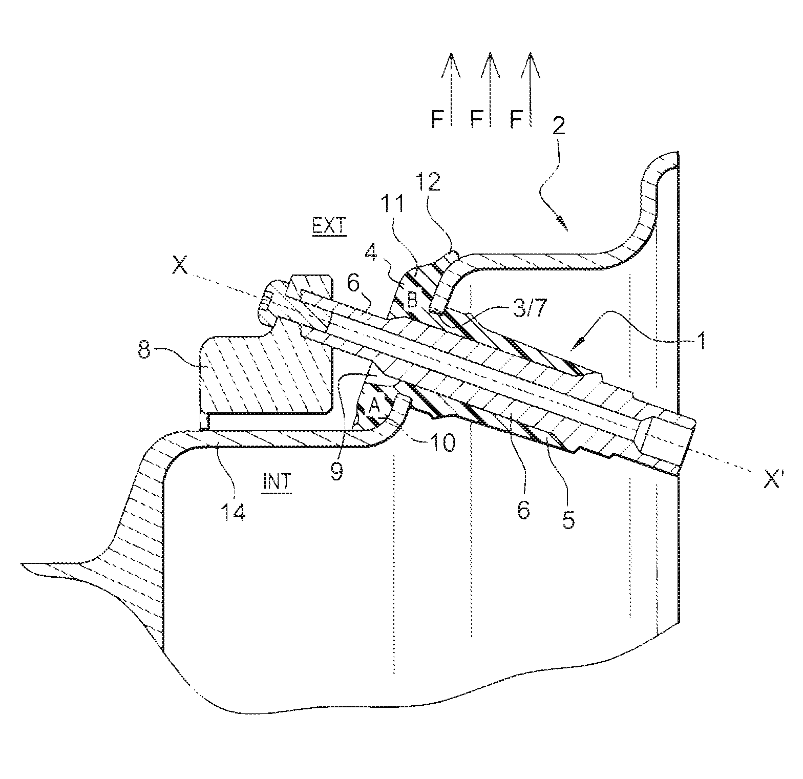
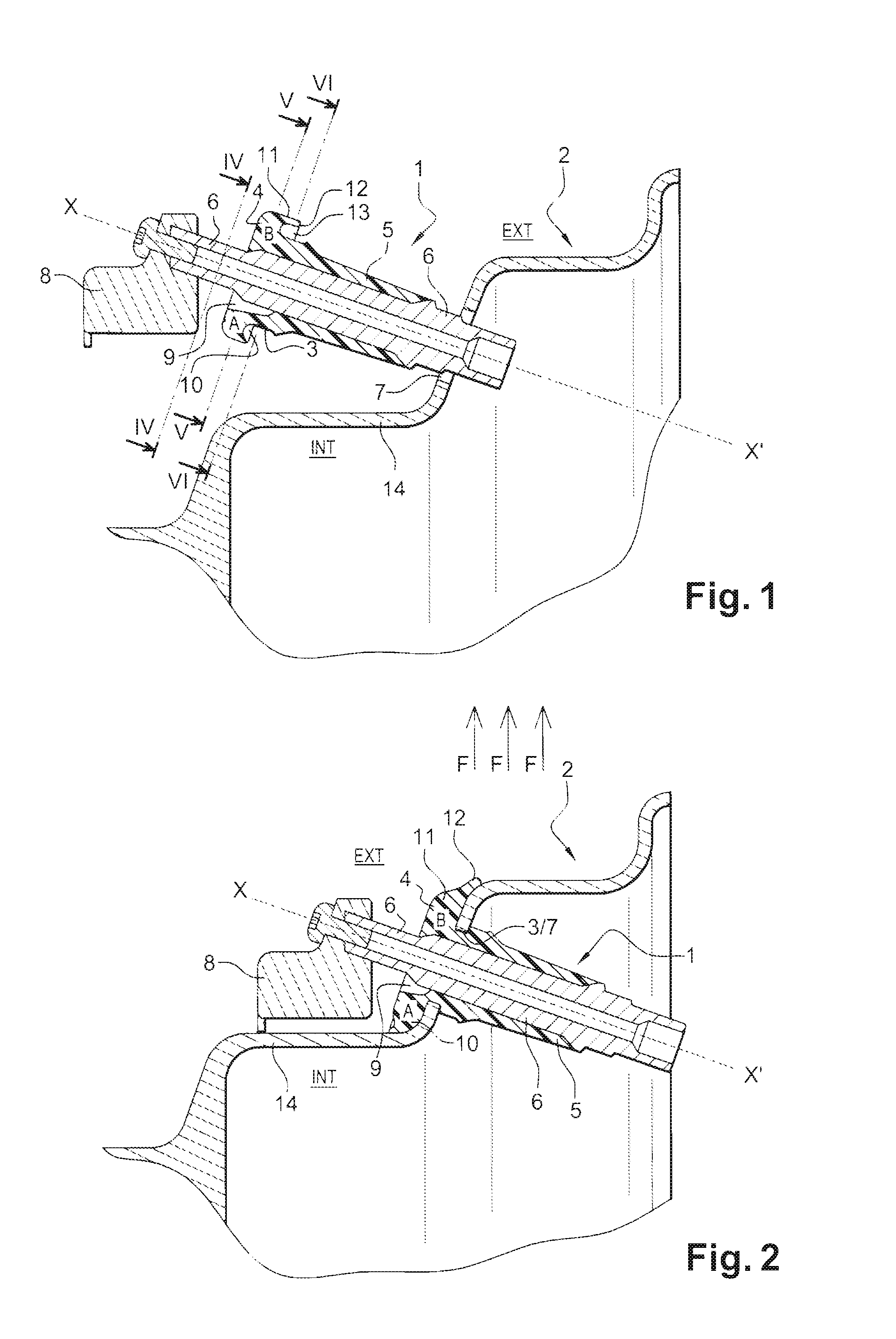
[0026]The valve 1 globally designated in FIGS. 1 and 2 is of the “Snap-In” type, intended to be mounted directly on the rim 2 of a vehicle wheel fitted with a “tubeless” tire.

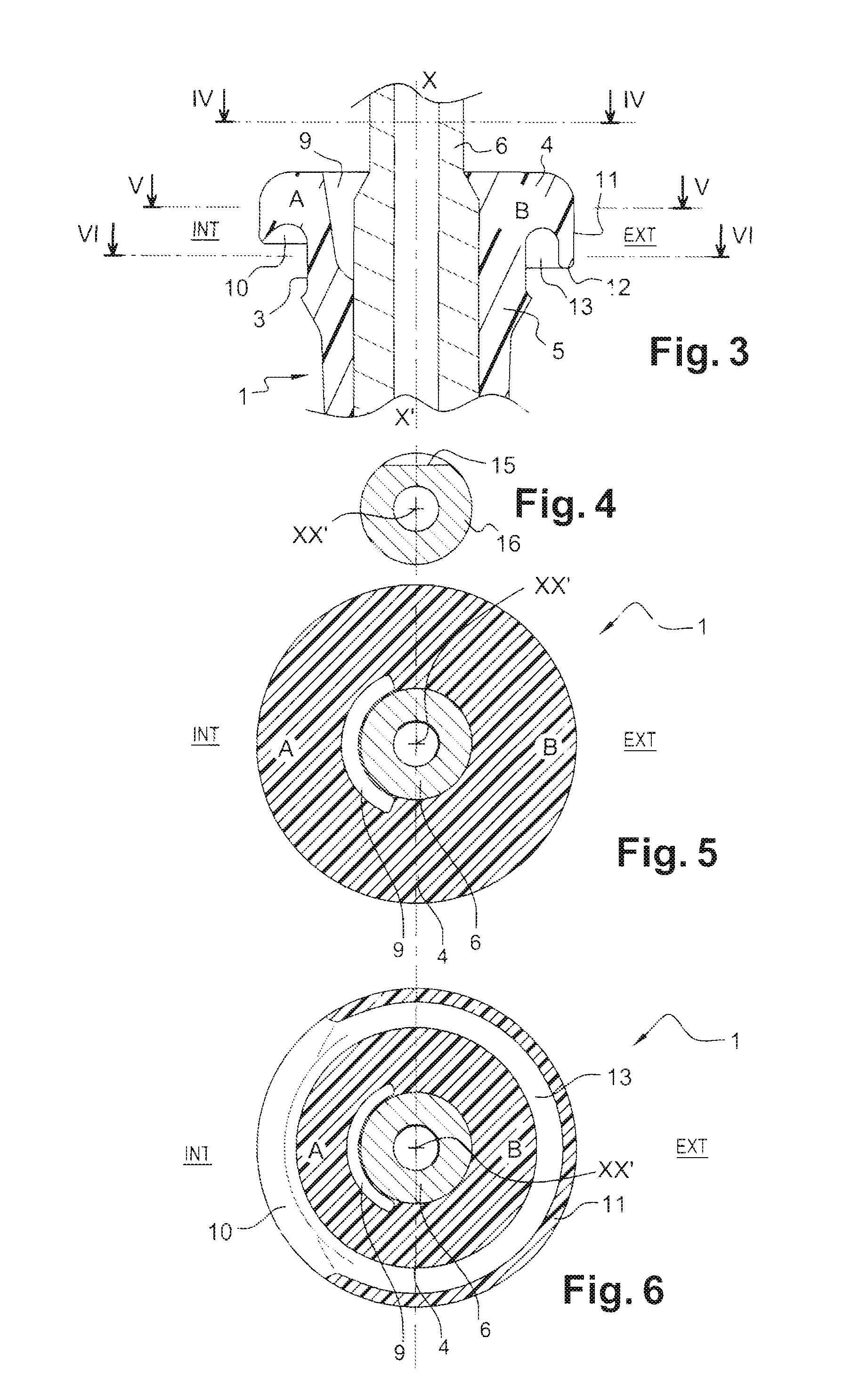
[0027]The valve 1 is secured to the rim 2 through which it passes by the intermediary of a groove 3 produced at the base of a bulb 4 extended by a rubbery coating 5 of an internal nozzle 6 of the valve 1. Said groove 3 cooperates elastically with a hole 7 in the rim 2, on the periphery of which it becomes housed.

[0028]According to this non-restricted embodiment, the valve 1 is associated with a pressure sensor housed in a box 8 located inside the tire.

[0029]According to the invention, the volumetric mass of the bulb 4 is smaller in its region “A” directed toward the interior “INT” of the rim 2, by comparison with its region “B” directed towards the exterior “EXT”, this reduction taking place in the vicinity of the groove 3, intended to cooperate with the hole 7 in the rim 2, in its portion that surrounds the no...


PUM


Abstract

A valve of the “Snap-In” type is intended to be mounted directly on the rim of a vehicle wheel fitted with a “tubeless” tire. The valve is secured to the rim through which it passes via a groove produced at the base of a bulb extended by a rubbery coating of an internal nozzle of the valve. The groove collaborates elastically with a hole in the rim, on the periphery of which hole it becomes lodged, the mass or the volume of the bulb being smaller in its region (A) toward the interior of the rim by comparison with its region (B) directed toward the exterior, this reduction taking place near the groove intended to collaborate with the hole in the rim, both in the part thereof that surrounds the nozzle and in the part thereof that is in contact with the bottom of the rim.

Description

BACKGROUND[0001]This invention relates to a valve intended to be mounted directly on the rim of a vehicle wheel fitted with a “tubeless” tire.[0002]Such a valve is secured to the rim through which it passes and it is known to carry it out using a threaded metal socket passing through the rim, and immobilized by a nut, by the intermediary of a seal.[0003]This has the disadvantage of having a high cost due to the multi-component effect, i.e. a nut, a seal and a valve. This also necessarily generates multiple manipulations during mounting or dismounting.[0004]Valves of the “Snap-In” type are also known, secured to the rim through which they pass by the intermediary of a groove produced at the base of a bulb extended by a rubbery coating of an internal nozzle of the valve, said groove cooperating elastically with a hole in the rim on the periphery of which it becomes housed by force, thanks to the elastic deformation of the groove.[0005]As such the valve can be mounted in a single opera...

Claims


Application Information

Patent Timeline
Patent Type & Authority Patents(United States)
IPC IPC(8): F16K15/20B60C29/00
CPCB60C23/0494B60C29/02Y10T137/3584Y10T137/3662Y10T137/3724
Inventor ROBERT, AURELIEN
Owner SCHREDER SA
Why Eureka
Try Eureka