Liquid storage container

a liquid storage container and liquid storage technology, applied in printing and other directions, can solve the problems of not achieving the above-described problems, affecting the flow of ink, and affecting the quality of ink, so as to reduce the pressure difference between the first liquid storage chamber and the second liquid storage chamber

Active Publication Date: 2014-09-02
SEIKO EPSON CORP
View PDF4 Cites 2 Cited by
  • Summary
  • Abstract
  • Description
  • Claims
  • Application Information

AI Technical Summary

Benefits of technology

[0009]An advantage of some aspects of the invention is to provide a liquid storage container capable of leading out liquid while reducing influence of bubbles.
[0011]Bubbles in the liquid easily stay at a portion which is bent in the liquid channel. With respect to this, according to this configuration, the bubbles positioned at the curved channel portion are introduced to the lead-out port side via the inclined channel portion. Accordingly, for example, there can be a less concern that bubbles staying in the curved channel portion may be grown and may block the liquid channel, and thus, the liquid can be led out while reducing influence of the bubbles.
[0015]According to this configuration, since bubbles generated in the ink chamber move in a direction that is opposite from the gravity direction, the channel opening is opened to the bottom surface, and thus, there can be a less concern that the bubbles may enter the liquid channel from the channel opening.
[0017]According to this configuration, the horizontally inclined rib portion is formed, and thus, the liquid storage chamber can be reinforced. Moreover, since the horizontally inclined rib portion extends along the direction intersecting the horizontal direction, when bubbles are generated in the liquid stored in the liquid storage chamber, the bubbles can move along the horizontally inclined rib portion. That is, there can be a less concern that the bubbles may be trapped by the horizontally inclined rib portion.
[0021]According to this configuration, since the cross-sectional area of the inclined channel portion is large, there can be a less concern that the inclined channel portion may be blocked by the bubbles generated in the curved channel portion.
[0025]According to this configuration, due to the ventilation opening formed in the partition wall, the pressure difference between the first liquid storage chamber and the second liquid storage chamber can be decreased. In addition, since the ventilation opening formed in the partition wall is formed to be closer to the filler port formation surface than the ventilation opening formed in the intersection rib portion, there can be a less concern that the liquid in the second storage chamber entering may enter the first liquid storage chamber from the ventilation opening.

Problems solved by technology

Accordingly, due to the bubbles, there is a concern that a channel of the ink may be blocked or flow of the ink may be hindered.
Moreover, the above-described problems occur not only in a liquid storage container which is included in an ink jet type printer but also in almost all liquid storage containers into which liquid can be poured.

Method used


Image

  • Liquid storage container
  • Liquid storage container
  • Liquid storage container

Examples


Embodiment Construction

[0056]Hereinafter, embodiments of a liquid storage container and an ink jet type printer (hereinafter, also referred to as a “printer”) which is an example of a liquid consumption apparatus which consumes liquid supplied from the liquid storage container will be described with reference to the drawings.

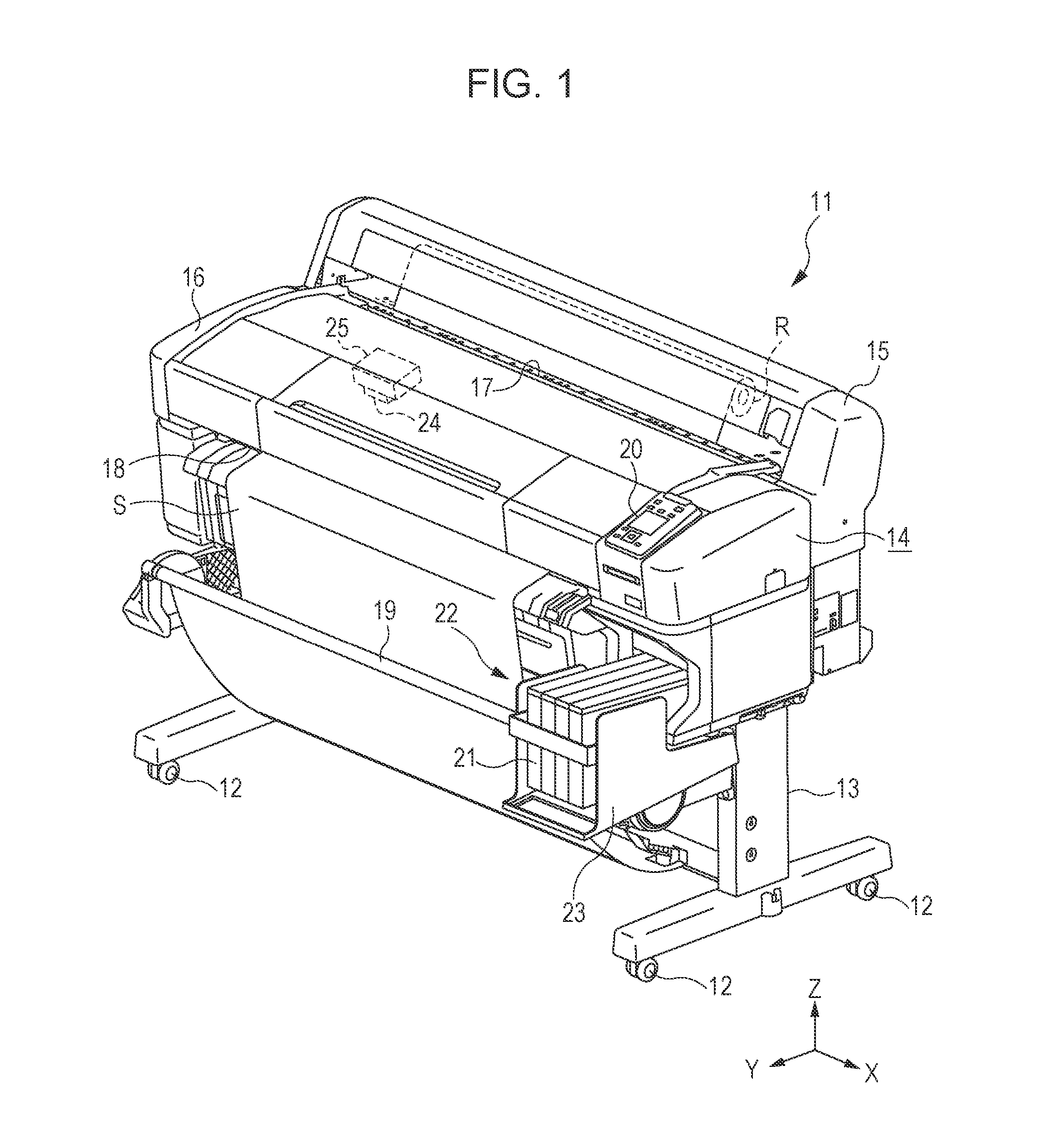
[0057]As shown in FIG. 1, a printer 11 of the present embodiment includes leg portions 13 to which wheels 12 are mounted to the lower ends and an apparatus main body 14 which is assembled on the leg portions 13 and has an approximately rectangular parallelepiped shape. Moreover, in the embodiment, a direction along the gravity direction is set to an up-down direction Z, and a longitudinal direction of the apparatus main body 14 which intersects (is orthogonal in the embodiment) the up-down direction Z is set to a left-right direction X. In addition, a direction which intersects (is orthogonal in the embodiment) both of the up-down direction Z and the left-right direction X is set to a...


PUM


Abstract

A liquid storage container includes a liquid storage body storing ink supplied to a printer consuming the ink. The liquids storage body includes an ink chamber which can store the ink, a filler port through which ink can be poured into the ink chamber, a lead-out port which leads out the ink stored in the ink chamber to the printer side, and a lead-out channel which connects a channel opening formed in the ink chamber and the lead-out port.

Description

[0001]Priority is claimed under 35 U.S.C. §119 to Japanese Application No. 2012-192655 filed on Aug. 31, 2012 which is hereby incorporated by reference in its entirety.BACKGROUND[0002]1. Technical Field[0003]The present invention relates to a liquid storage container which stores liquid to be supplied to a liquid consumption apparatus.[0004]2. Related Art[0005]In the related art, as a type of liquid consumption apparatus, an ink jet type printer is known which ejects ink (liquid) from a liquid ejecting head to a target such as a paper and thus, performs printing (recording). Moreover, in the aforementioned printer, when a relatively large amount of ink is consumed and the printing is performed, in order to supply the ink to the liquid ejecting head continuously and stably, a configuration which supplies ink from a liquid storage container with a relatively large ink storage capacity to the liquid ejecting head is known.[0006]For example, in a printer disclosed in JP-A-2012-51307, a ...

Claims


Application Information

Patent Timeline
Patent Type & Authority Patents(United States)
IPC IPC(8): B41J2/175
CPCB41J2/1752B41J2/17546B41J2/17523B41J2/17553
Inventor IWAMURO, TAKESHIKODAMA, HIDETOSHI
Owner SEIKO EPSON CORP
Why Eureka
Try Eureka