Keyswitch structure mounted within a circuit board and baseplate

a circuit board and key switch technology, applied in the direction of tactile feedback, contact mechanisms, electrical devices, etc., can solve the problems of high maintenance cost, difficult to be repaired, easy damage to the membrane switch, etc., and achieve the effect of promoting the repairability of individual keys and enhancing the tactile feedback

Active Publication Date: 2018-04-10
DARFON ELECTRONICS (SUZHOU) CO LTD +1
View PDF23 Cites 7 Cited by
  • Summary
  • Abstract
  • Description
  • Claims
  • Application Information

AI Technical Summary

Benefits of technology

[0007]In view of the prior arts, it is an object of the present invention to provide a keyswitch structure, which utilizes a mechanical switch to enhance the tactile feedback and to promote the repairability of individual key.
[0009]It is a further object of the invention to provide a keyswitch structure, which has the baseplate designed with an opening for accommodating parts of the key to effectively reduce the key height.
[0014]In an embodiment, the circuit board is a rigid circuit board. When the keycap moves toward the baseplate to trigger the mechanical switch in response to a pressing force, the rigid circuit board is capable of sustaining the pressing force transferred by the mechanical switch without deforming downward.

Problems solved by technology

However, the membrane switch is readily damaged due to frequent operation or application of improper force and is difficult to be repaired.
Moreover, when one of the trigger circuits in the membrane switch corresponding to a certain keyswitch is broken, the entire membrane switch of a keyboard have to be replaced, resulting in high maintenance cost.
In addition, when the user presses the keycap to trigger the membrane switch, the tactile feedback is reduced since the click of keystroke is not clear, resulting in unsatisfied manipulation for gamers.
Therefore, how to reinforce the tactile feedback and effectively reduce the key height is one of the important issues.

Method used


Image

  • Keyswitch structure mounted within a circuit board and baseplate
  • Keyswitch structure mounted within a circuit board and baseplate
  • Keyswitch structure mounted within a circuit board and baseplate

Examples


Embodiment Construction

[0029]The invention provides a keyswitch structure, which can be applied to any pressing type input device including keyboard to enhance the tactile feedback, effectively reduce the key height, or promote the repairability of individual key. Hereafter, the keyswitch structure of the invention will be described in detail with reference to the drawings.

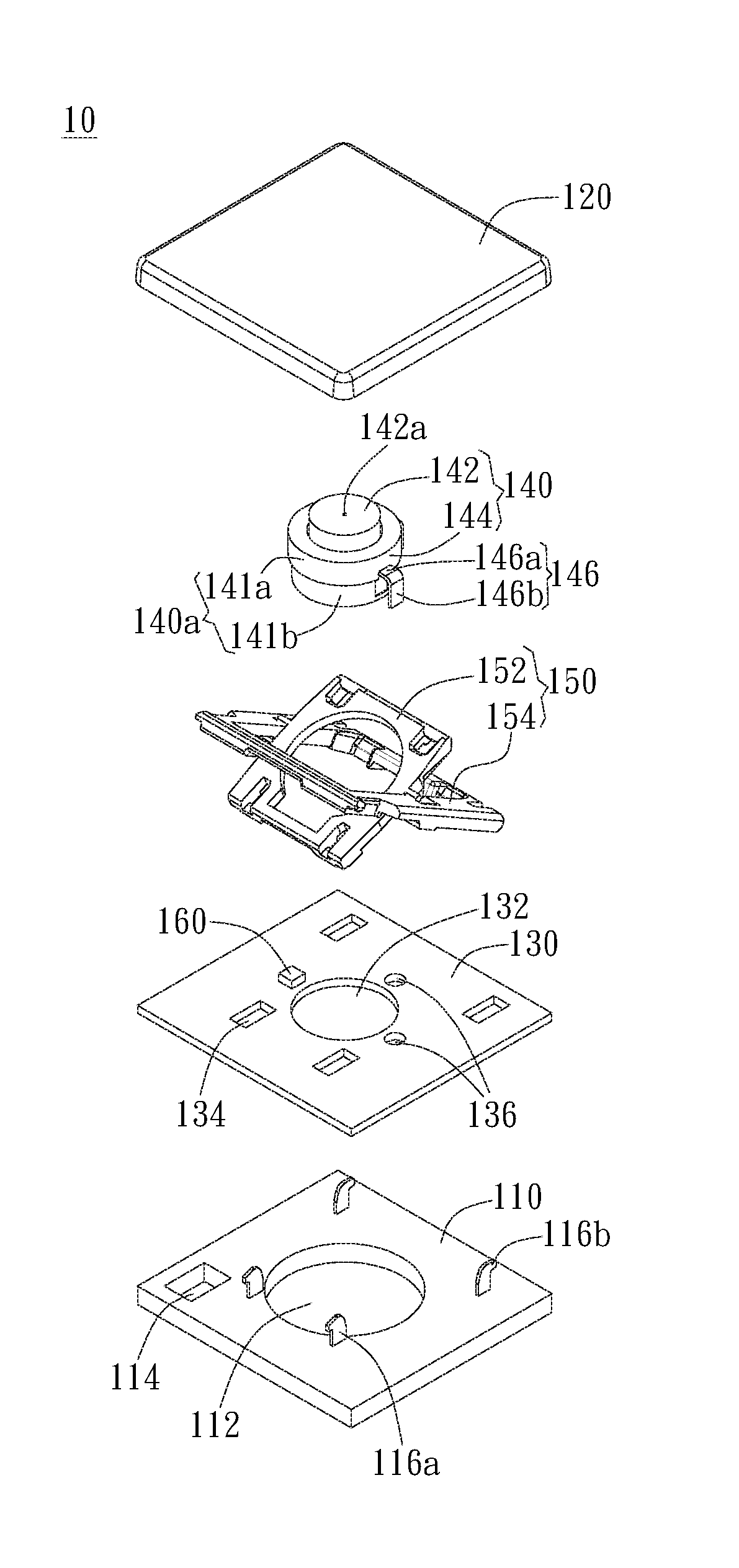
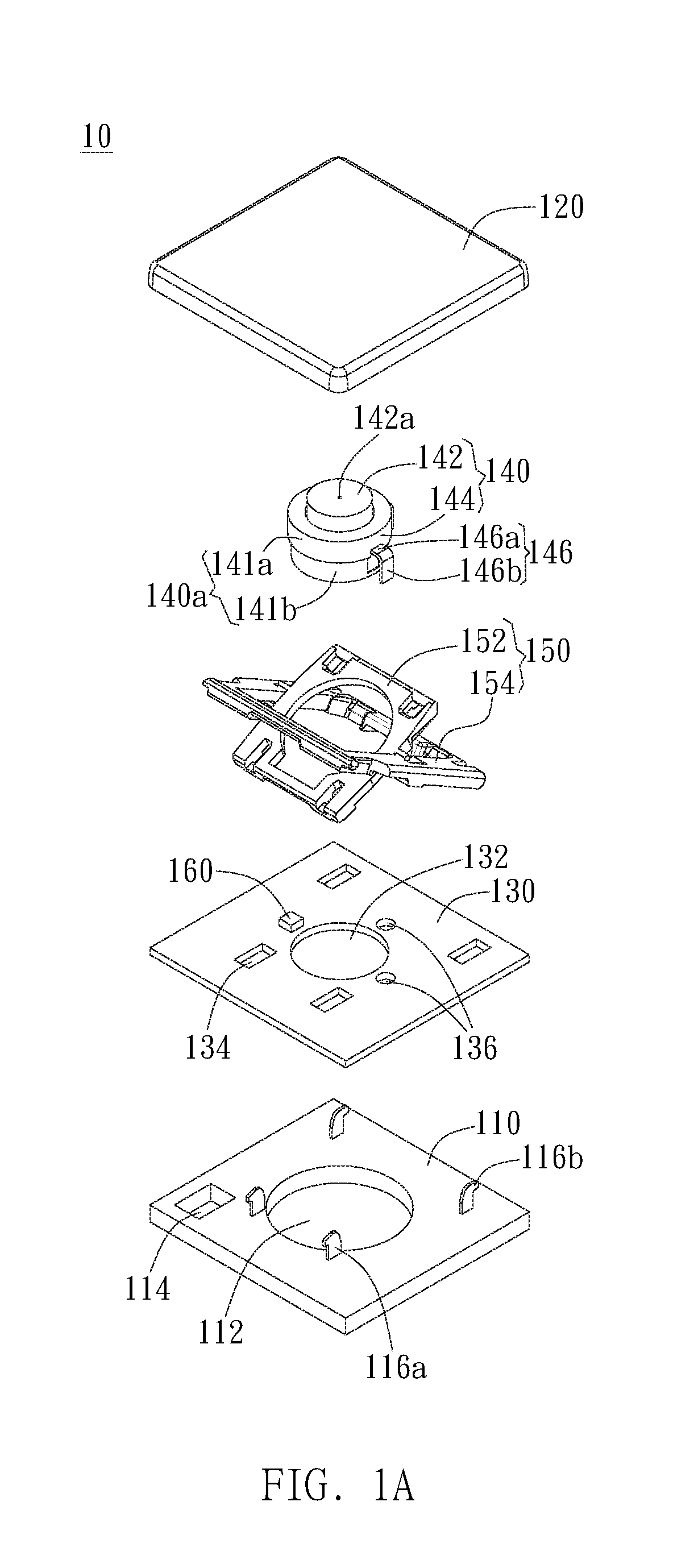
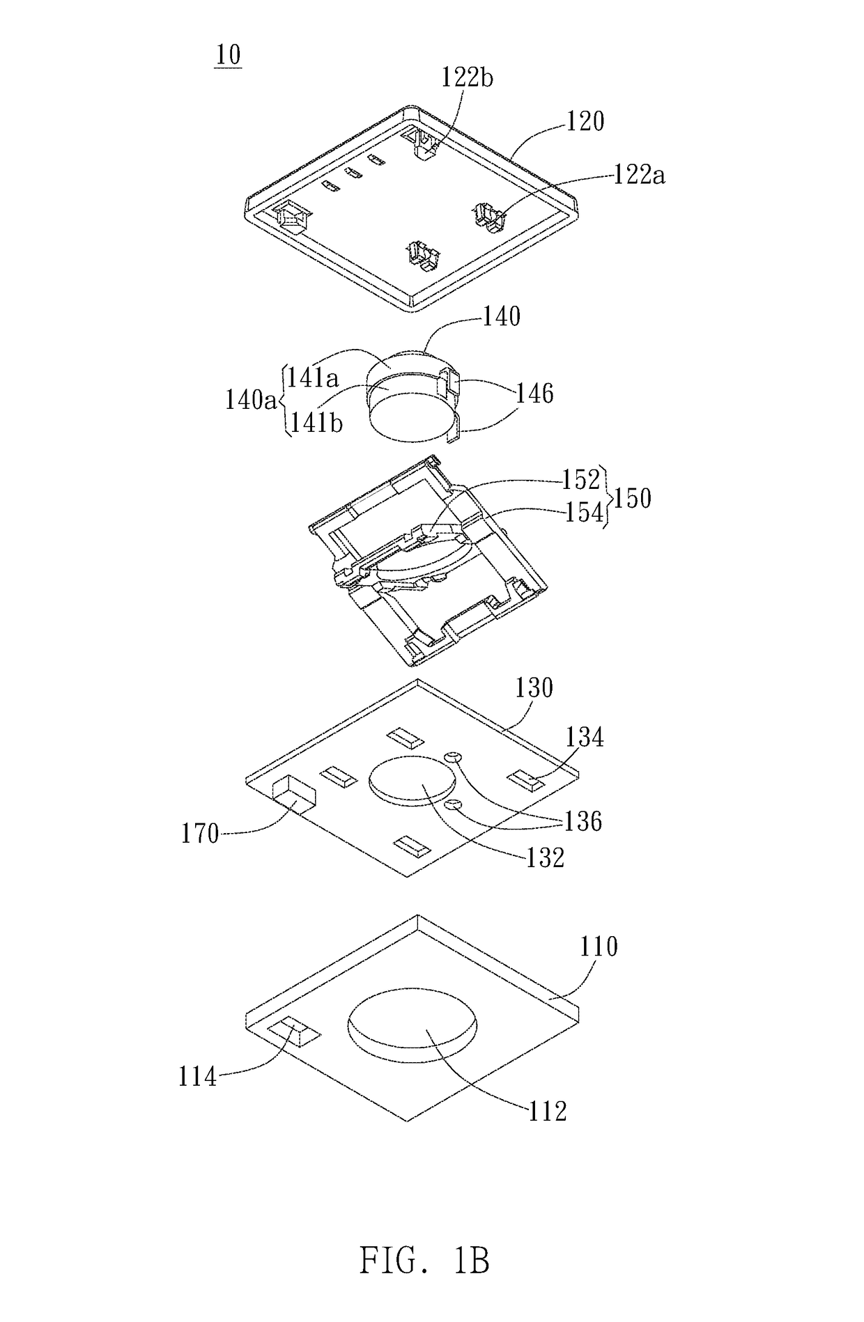
[0030]As shown in FIGS. 1A to 1D, in an embodiment, the keyswitch structure 10 includes a baseplate 110, a keycap 120, a circuit board 130, and a mechanical switch 140. The baseplate 110 has a switch opening 112. The keycap 120 is movably disposed above the baseplate 110. The circuit board 130 is disposed on the baseplate 110 and has a through hole 132 and at least one pin hole 136. The mechanical switch 140 is disposed below the keycap 110 and extends through the through hole 132 to be at least partially received in the switch opening 112. The mechanical switch 140 is electrically coupled to the circuit board 130. When the keycap 120 m...


PUM


Abstract

A keyswitch structure includes a baseplate having a switch opening, a keycap movably disposed above the baseplate, a circuit board disposed on the baseplate, the circuit board having a through hole, and a mechanical switch disposed below the keycap, the mechanical switch extending through the through hole to be partially received in the switch opening and electrically coupled to the circuit board, wherein when the keycap moves toward the baseplate, the keycap triggers the mechanical switch.

Description

BACKGROUND OF THE INVENTION[0001]1. Field of the Invention[0002]The invention generally relates to a keyswitch structure. Particularly, the invention relates to a keyswitch structure capable of promoting tactile feedback and effectively reducing key height.[0003]2. Description of the Prior Art[0004]Conventional keyboards usually use membrane switches as signal-generating elements. In general, the membrane switch consists of an upper circuit layer, a lower circuit layer, and a spacer between the upper circuit layer and the lower circuit layer. The upper circuit layer and the lower circuit layer have corresponding switch contacts as a trigger circuit of the keyswitch. When the keycap is pressed to trigger the membrane switch, the upper circuit layer is deformed, so the switch contact on the upper circuit layer contacts the corresponding switch contact on the lower circuit layer, and the membrane switch is conducted to generate a trigger signal. However, the membrane switch is readily ...

Claims


Application Information

Patent Timeline
Patent Type & Authority Patents(United States)
IPC IPC(8): H01H13/14H01H13/02
CPCH01H13/14H01H13/023H01H2215/00H01H3/125H01H13/7006H01H13/85H01H2219/036H01H2223/054H01H2227/036H01H13/705
Inventor LIU, CHIA-HUNG
Owner DARFON ELECTRONICS (SUZHOU) CO LTD
Why Eureka
Try Eureka