Portable path light system and method

a path light and solar energy technology, applied in the field of outdoor lighting systems, can solve the problems of limiting the use of typical path lighting systems to yard/dirt locations, cumbersome and heavy large battery operated path lights, and little progress in improving the portability of stationary, stake-mounted pathway lights, etc., and achieves tighter fitting

Active Publication Date: 2018-05-15
ROOD JOHN DANIEL
View PDF13 Cites 2 Cited by
  • Summary
  • Abstract
  • Description
  • Claims
  • Application Information

AI Technical Summary

Benefits of technology

[0011]Shims may include a flange, curved or straight, at the bottom of the shim. The flange forms a corner whereby the mating cavity fits into the corner. The flange may vertically support the base. The flange may prevent the pole from being lifted out of the base and system, and otherwise secure the pole in place.
[0013]An adhesive may be used to connect the shims to one another, to the pole, and / or to the cavity of the base. Preferably, the adhesive includes a two-sided adhesive tape, preferably at least 20-lb rated, or otherwise as is known and / or preferred in the art. In one embodiment, a stake may be affixed to the bottom of the vertical pole to provide additional horizontal and / or torsional support (to keep the system from falling over).
[0016]In one alternative embodiment, a stake can be affixed to the pole before or alter the system is completed. The stake further secured the light system to the ground surface. A second shim may be piggy-backed atop the first shim to expand the diameter of the pole and shim system to better mate with the collar bore. A third, fourth, or more shims may be piggy-backed successively atop the initial shim to provide a tighter fit, wedge system, or the like.

Problems solved by technology

Large battery operated path lights were cumbersome and heavy, and therefore often hard-installed in a single location.
Little progress has been made to improve the portability of stationary, stake-mounted pathway lights.
This retrofit installation procedure limits the use of typical path lighting systems to yard / dirt locations, available for the stake to be secured.
Furthermore, this stake mounting system is almost often flimsy, and / or may be installed crooked, because the stake rarely goes into the ground perfectly straight.

Method used


Image

  • Portable path light system and method
  • Portable path light system and method
  • Portable path light system and method

Examples


Embodiment Construction

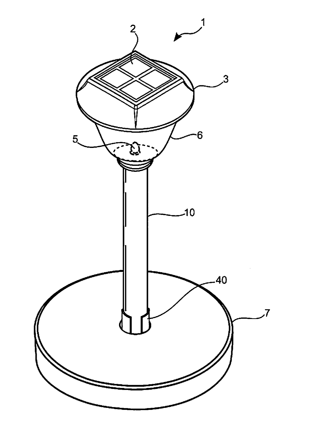
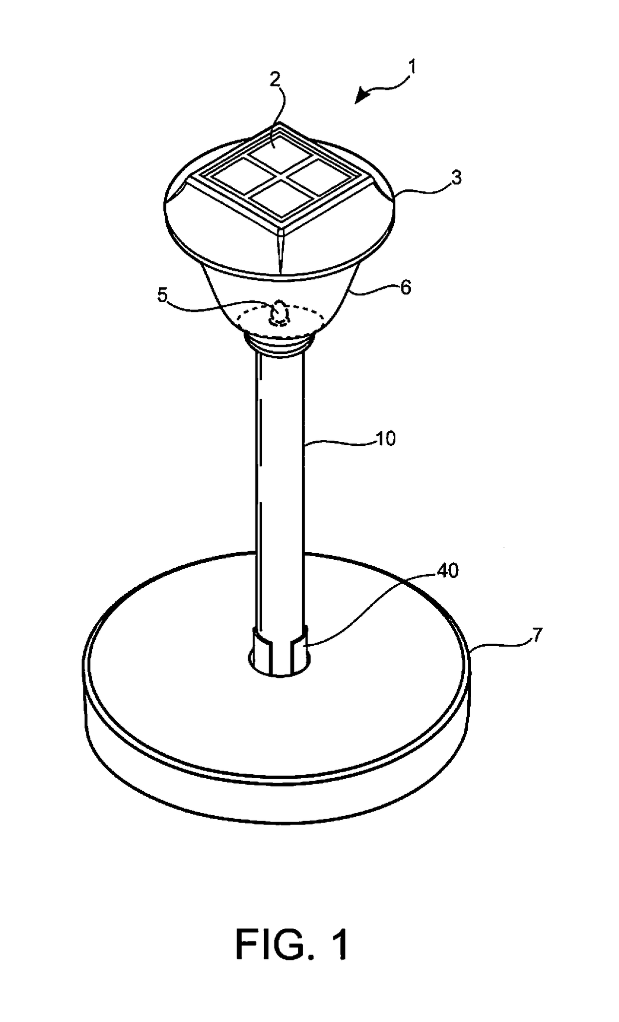
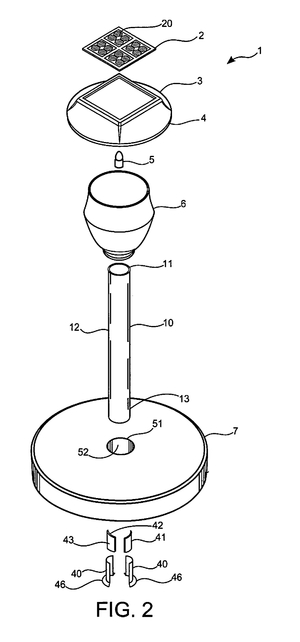
[0038]The present invention includes a Portable Path Light System (PPLS) for solar type pathway lights. PPLS changes the means by which the light post is supported. The PPLS can be used with or without a grounding stake. PPLS changes the means by which the light post is supported. PPLS can eliminate the need for a stake by adding a heavy, more secure, base to the bottom of a light post. PPLS is preferably comprised of heavy material such as concrete, iron, or the like, with a hole through the center to accommodate a support pole therein. This center hole acts as, and makes the base, a “collar” and is used to hold or lock the post in place. With a heavy base secured to the light post, the once stationary “staked light” becomes a portable light. PPLS no longer requires a stake (and soft / dirt ground support) for mounting. PPLS can be used on stairways, tables, walls, sidewalks, . . . anywhere a light is needed, PPLS can be positioned in a location to collect (and store) solar light, or...


PUM


Abstract

A portable path light system including a stabilizing base collar to provide downward pressure and torsional stabilization. The collar is affixed to the poll by one or more, preferably tapered wedging shims. Shims may include flanges to provide for mating with the collar and / or support of the system. Nesting shims can help size, fit, and further support the system. Shims may be rotated to provide a more complete mating with collar.

Description

CLAIM OF PRIORITY[0001]The present application is related to and claims priority from prior provisional application Ser. No. 62 / 102,799, filed Jan. 13, 2015, and prior fried design patent application Ser. No. 29 / 524,446, filed Apr. 20, 2015 which applications are herein incorporated by reference.FIELD OF THE INVENTION[0002]The present invention relates to outdoor lighting systems. More particularly, the present invention relates to portable solar lighting systems.BACKGROUND OF THE INVENTION[0003]Solar pathway lights are a fairly new concept. Before solar path lights, all path lights were wired for electricity, or powered by short term batteries. Being wired, pathway lighting systems were fixed in locations and wires were hidden in the ground—effectively preventing the portability of the lights. Often, an in-ground stake was necessary and beneficial for the permanent installations. Large battery operated path lights were cumbersome and heavy, and therefore often hard-installed in a s...

Claims


Application Information

Patent Timeline
Patent Type & Authority Patents(United States)
IPC IPC(8): F21L4/00F21L4/08F21V21/06
CPCF21L4/08F21V21/06
Inventor ROOD, JOHN DANIEL
Owner ROOD JOHN DANIEL
Why Eureka
Try Eureka