
Outdoor 2 multiply 27.5 kV solid-sealing vacuum modular device of electrified railway
An electrified railway and modularization technology, applied in the direction of electrical components, high-voltage air circuit breakers, circuits, etc., can solve the problems of large area of switchgear, large impact of external environment, poor product reliability, etc., to reduce the number of insulating pillars, Reduced footprint and the effect of reducing insulating struts
Patent Information
- Authority / Receiving Office
- CN · China
- Patent Type
- Patents(China)
- Current Assignee / Owner
- Publication Date
- 2011-01-26
Smart Images
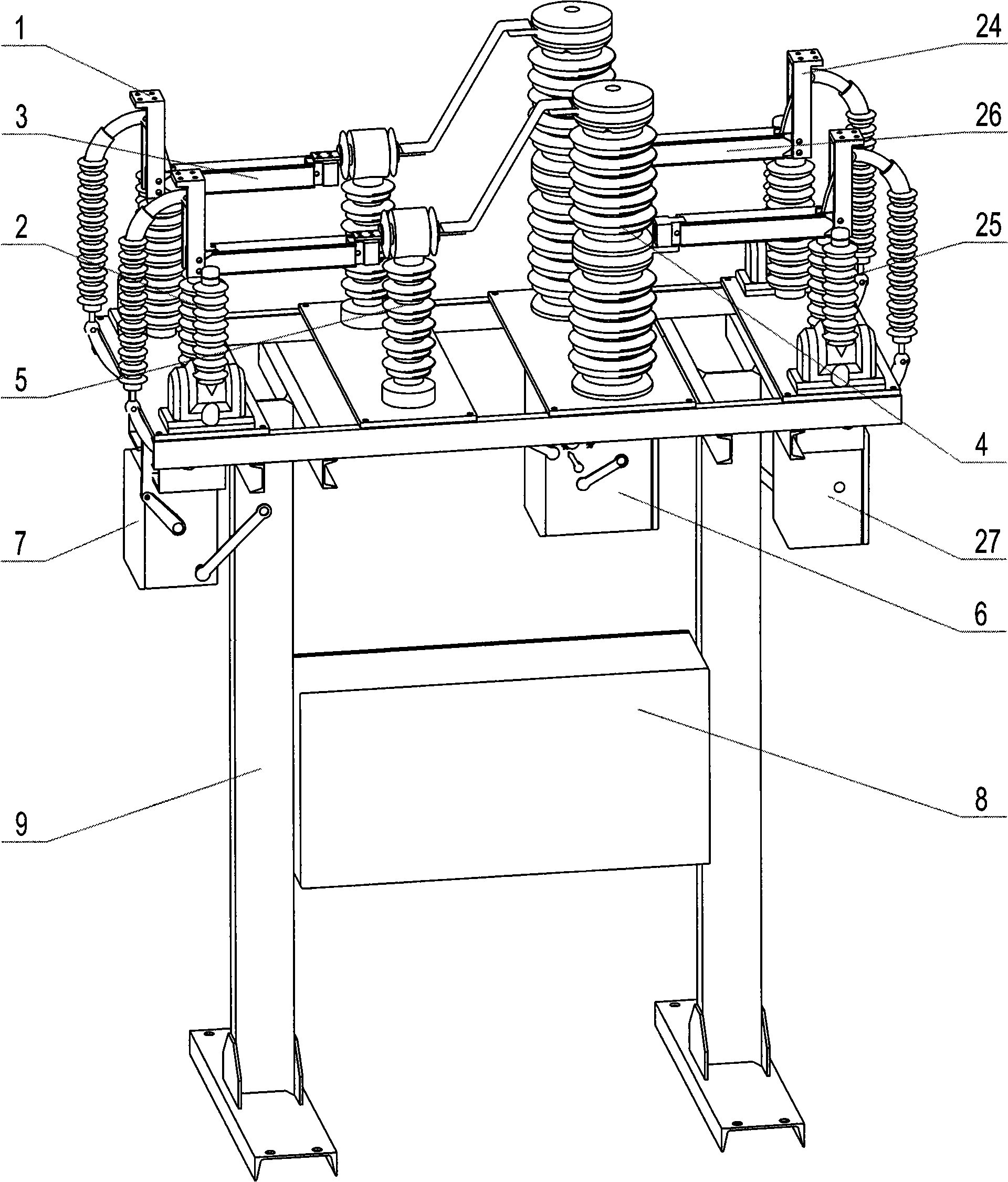
Figure 1 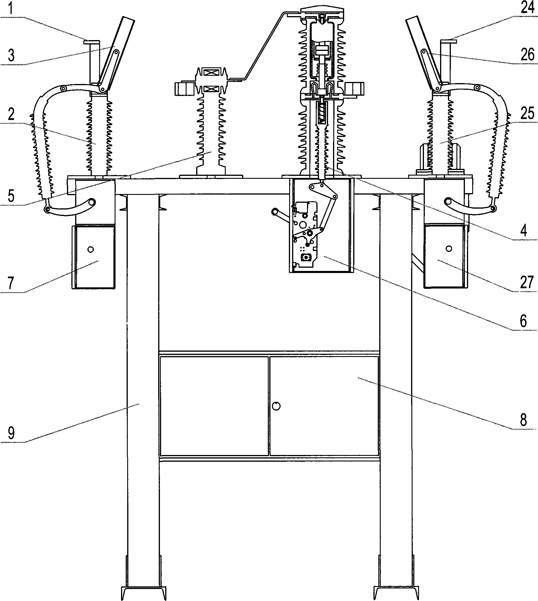
Figure 2 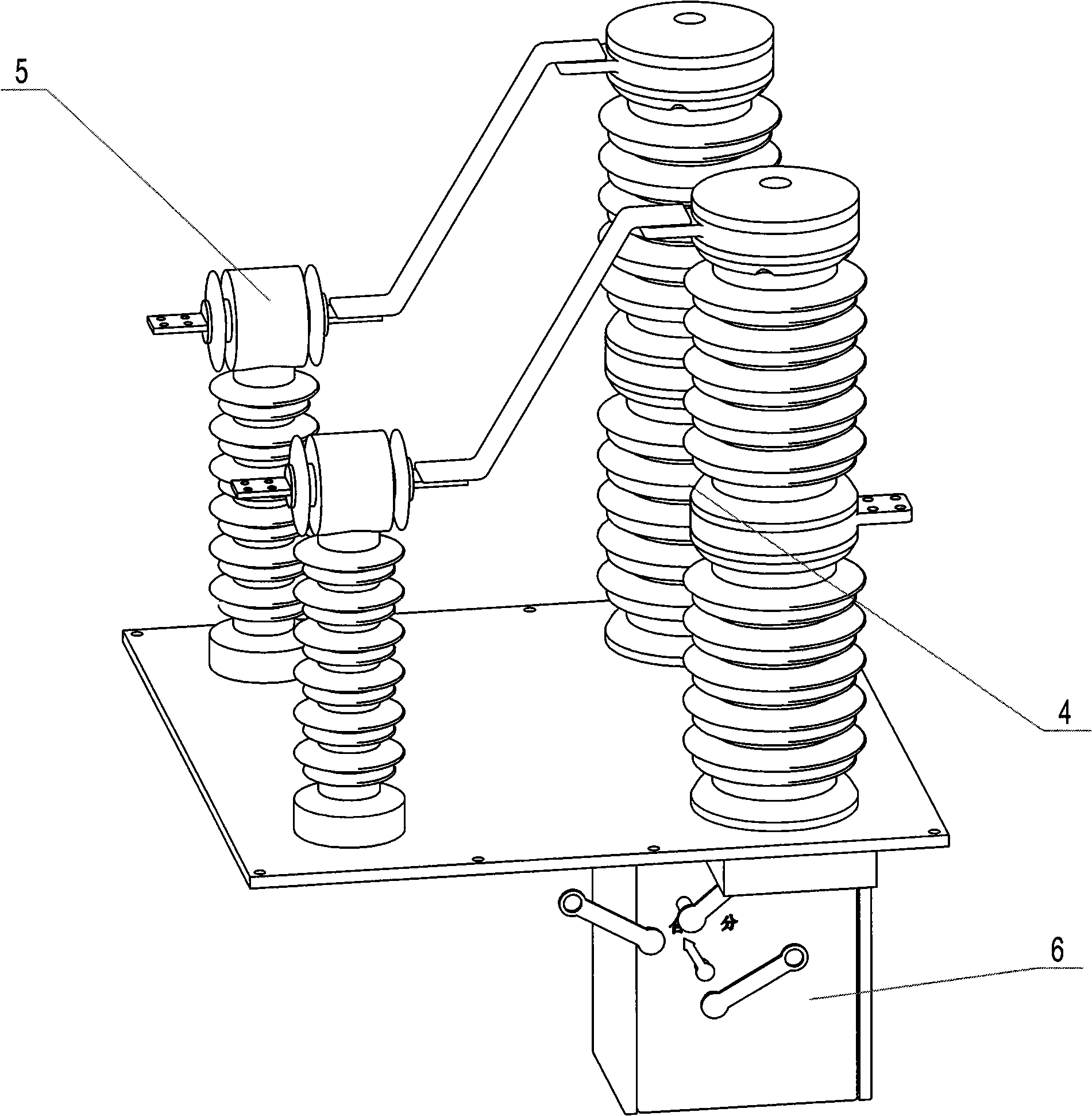
Figure 3
Abstract
Description
technical field
[0001] The invention relates to a special switchgear for 2×27.5kV electrified railway in AT power supply mode. Background technique
[0002] At present, the switchgear of electrified railway traction substations, divisional substations and AT substations are 2×27.5kV circuit breakers, voltage transformers, current transformers, bipolar isolating switches and other main equipment except for feeder bipolar isolating switches and anti-lightning coils. Arranged outdoors, others are arranged indoors with GIS inflatable switchgear, all of which need to be equipped with production houses to meet product use requirements. The 27.5kV incoming and outgoing lines in the high-voltage room adopt the cable entry (exit) method. Since there are many high-voltage cables in the incoming and outgoing lines, it is necessary to set up a cable interlayer under the production house to meet the cable laying requirements. Although this arrangement has high power supply reliability, ...
Examples
Embodiment Construction
[0033] The present invention will be further described below in conjunction with the accompanying drawings.
[0034] refer to Figure 1 ~ Figure 4, an outdoor 2×27.5kV solid-sealed vacuum modular electrical appliance for electrified railways, including a bracket 9, two parallel and independent connecting branches installed on the bracket 9, and an integrated automation control box 8, the The connecting branch includes a bipolar sealed vacuum circuit breaker 4, a first bipolar isolating switch 3, a second bipolar isolating switch 26, a solid-sealed prop current transformer 5, a first solid-sealed prop transformer 2, a second Two solid-sealed post-type transformers 25, incoming line connection terminals 24, and outgoing line connection terminals 1; the bipolar solid-sealed circuit breaker 4 is installed in the middle of the bracket 9, and the incoming line connection terminals 24 and outgoing line connection terminals 1 are respectively located Both sides of the bracket 9; the ...