
Fuel cell humidifier
A fuel cell and humidifier technology, applied in fuel cells, fuel cell additives, electrochemical generators, etc., can solve the problems of high energy consumption, excessive humidification, large membrane area and number of sheets, etc., and achieve low energy consumption , fast humidification effect
Patent Information
- Authority / Receiving Office
- CN · China
- Patent Type
- Patents(China)
- Current Assignee / Owner
- Publication Date
- 2012-11-21
Smart Images
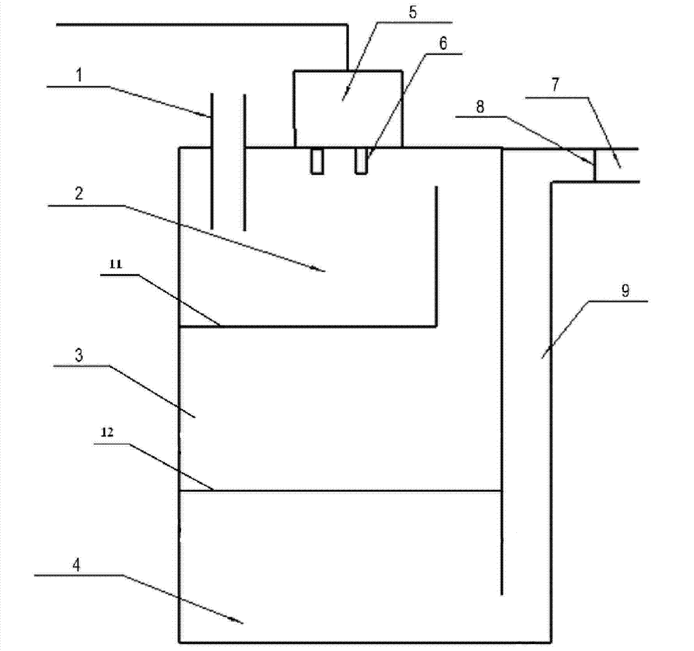
Figure 1 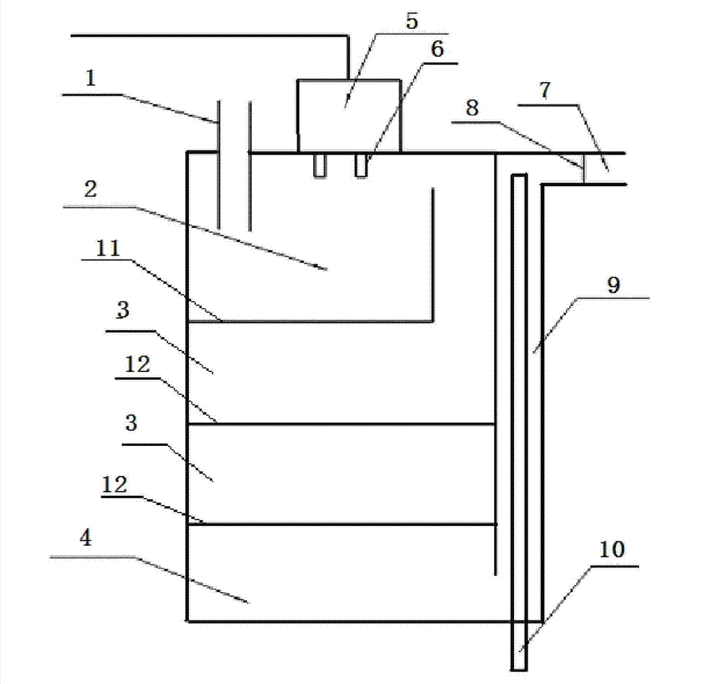
Figure 2 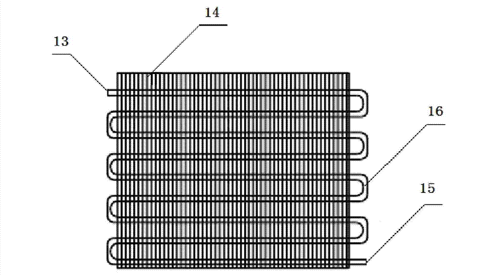
Figure 3
Abstract
Description
technical field
[0001] The invention relates to a fuel cell humidifier. Background technique
[0002] A fuel cell is a device that converts chemical energy into electrical energy through fuel combustion reactions in the battery. The negative electrode serves as the common interface between the fuel and the electrolyte, and also catalyzes the oxidation reaction of the fuel; while the positive electrode is the common interface between oxygen and the electrolyte. Catalyzes the reduction reaction of oxygen. Fuel cells are divided into phosphoric acid type (PAFC, phosphate fuel cell), molten carbonate type (MCFC, melt carbonate fuel cell), solid oxide type (SOFC, solidoxide fuel cell) and proton exchange membrane type (PEMFC, proton exchange membrane fuel cell). Among them, the proton exchange membrane fuel cell (PEMFC) can work in a low temperature environment. Because it uses a solid electrolyte, it can be applied to industries that require mobile energy, such as the automobi...
Examples
Embodiment Construction
[0021] The technical solutions of the present invention will be further described in detail through the following examples in conjunction with the accompanying drawings, but are not limited to the content of this example.
[0022] Such as figure 1 , figure 2 As shown, a fuel cell humidifier includes a gas-liquid exchange area 2, a heat exchange area 3 located at its lower part, and a nozzle control area 5 located at its upper part, wherein the upper part of the gas-liquid exchange area 2 is provided with a gas inlet 1. The heat exchange area 3 communicates with the lower part of the gas outflow part 9, and the gas outlet 7 is provided on the upper part of the gas outflow part 9.
[0023] The gas-liquid exchange area 2 is provided with a porous sieve plate 11, and the nozzle control area 5 is provided with a combination nozzle 6, and its flow rate can be manually controlled by switching nozzles of different apertures and adjusting water pressure, or by a solenoid valve. Take...