
Infrared radiation humidification device and method
A humidification device and infrared radiation technology, applied in heating methods, air humidification systems, exposure devices for photo-plate making process, etc., can solve the problems of uncontrollable humidification, narrow temperature application range, and low control efficiency
Patent Information
- Authority / Receiving Office
- CN · China
- Current Assignee / Owner
- Publication Date
- 2020-10-30
Smart Images
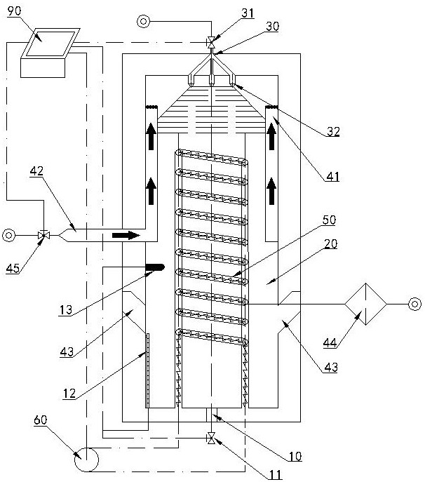
Figure 1 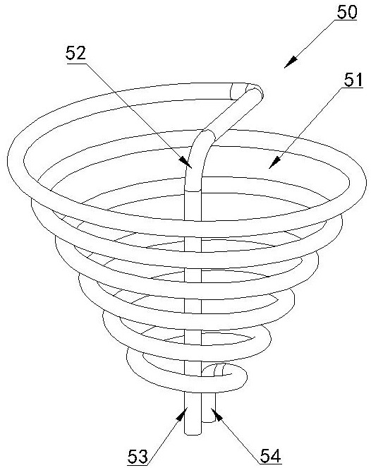
Figure 2 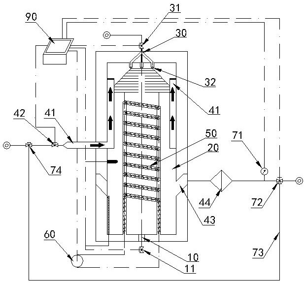
Figure 3
Abstract
Description
technical field
[0001] The invention relates to a gas humidification equipment, in particular to a humidification device and a humidification method used in semiconductor industry production with high cleanliness ambient gas requirements. Background technique
[0002] In many occasions in the semiconductor industry production, it is necessary to use high-clean gas, and the adjustment and control of the humidity of the gas is also one of the common gas treatment processes. For example, the applicant mentioned in the Chinese invention patent with application number 201711395951.3 that the immersion lithography machine supplies air with high relative humidity above the silicon wafer to weaken the evaporation of the immersion liquid on the silicon wafer and prevent the occurrence of out of shape. The existing traditional gas humidification technologies mainly include: ultrasonic atomization humidification, packed tower bubbling humidification and spray cooling humidification; a...
Examples
Embodiment 1
[0031] figure 1In the shown embodiment, an infrared radiation humidifying device includes an evaporation chamber 2, a liquid-phase water supply device 30, a carrier flow channel and a controller 90, and the liquid-phase water supply device 30 includes a liquid supply control valve 31 and an atomizing The nozzle 32 also includes an infrared heater 50 and an infrared controller 60. The main cavity is an evaporation chamber processed from clean, heat-insulating, and high-temperature-resistant materials; the infrared controller 60 is used to provide the infrared heater 50 with infrared-generated external heating Controlled infrared waves, the infrared heater 50 is installed inside the evaporation chamber 20, and the infrared heater is used to provide infrared waves to vaporize the liquid phase water; the carrier flow channel includes a dry gas inlet 42 and a wet gas outlet 43, wherein the dry gas inlet 42 One end located inside the evaporation chamber 20 is installed with an air f...
Embodiment 2
[0033] figure 2 In the shown embodiment, the infrared heater 50 adopts an inverted conical helix shape with a large top and a small bottom. Of course, it can also be a conical helix shape with a small top and a large bottom, or a double-sided spiral with a small middle part and a large top and bottom ends. Cone helix shape. When adopting an inverted tapered helix shape with a large top and a small bottom, the first heating connection end 53 and the second heating connection end 54 of the infrared heater 50 are vertically arranged in parallel and drawn out from the lower bottom end of the entire infrared heater 50 external location (see figure 2 ), wherein the first heating connection end 53 extends upwards and runs through the helical-shaped inner bucket-shaped channel 51 formed by the entire infrared heater 50, and then starts from the upper end 52 of the first heating connection end 53 to perform upward, downward and small Helically extending to connect with the upper en...
Embodiment 3
[0035] image 3 In the shown embodiment, a relative humidity sensor 71 and an outlet three-way valve 72 are arranged on the body output flow, and both the relative humidity sensor 71 and the outlet three-way valve 72 are electrically connected to the controller; the relative humidity sensor 71 is used for monitoring gas The relative humidity of the gas on the output flow path, the outlet three-way valve 72 is used to adjust the output gas flow rate according to the temperature and humidity data information detected by the humidity sensor 71 . Part or all of the output gas is reintroduced into the dry gas inlet 42 through the inlet three-way valve 74 along the return flow path 73, so that the relative humidity of the gas is readjusted. Others are identical with embodiment 1 or embodiment 2.