
Power generating guide rail
A technology of guide rails and sleepers, applied in the field of rail car guide rails, can solve the problems of multiple steel materials, increased costs, and high laying costs, and achieve the effect of broad application prospects and outstanding benefits
Patent Information
- Authority / Receiving Office
- CN · China
- Patent Type
- Applications(China)
- Current Assignee / Owner
- Publication Date
- 2010-10-06
- Estimated Expiration
- Not applicable · inactive patent
Smart Images
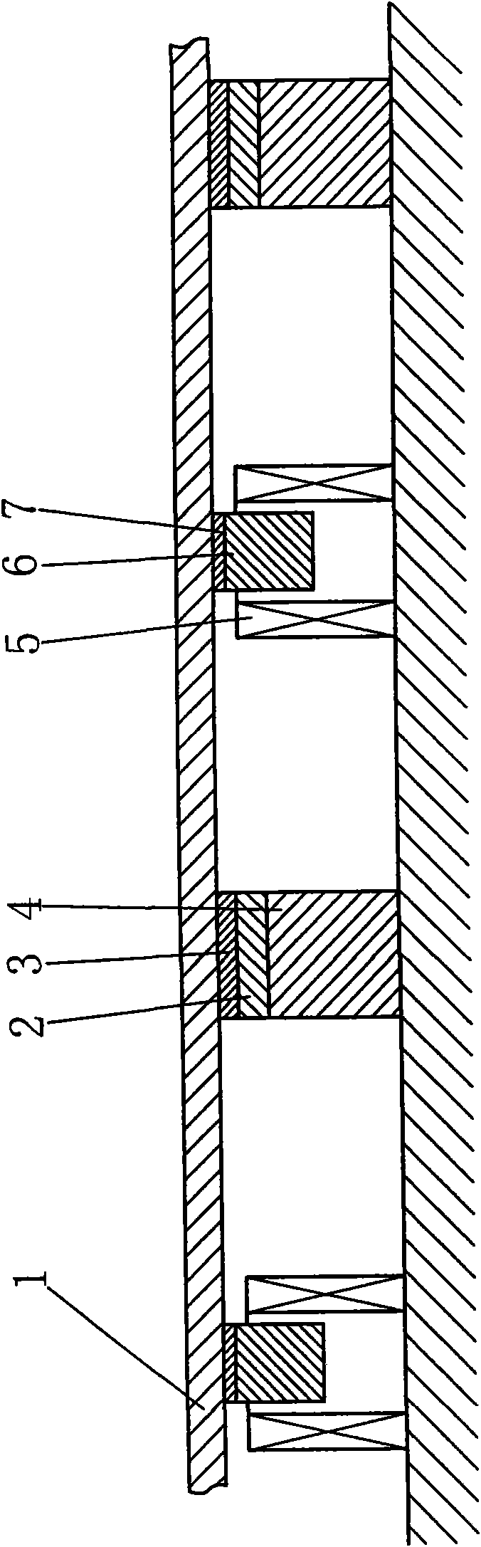
Figure 1 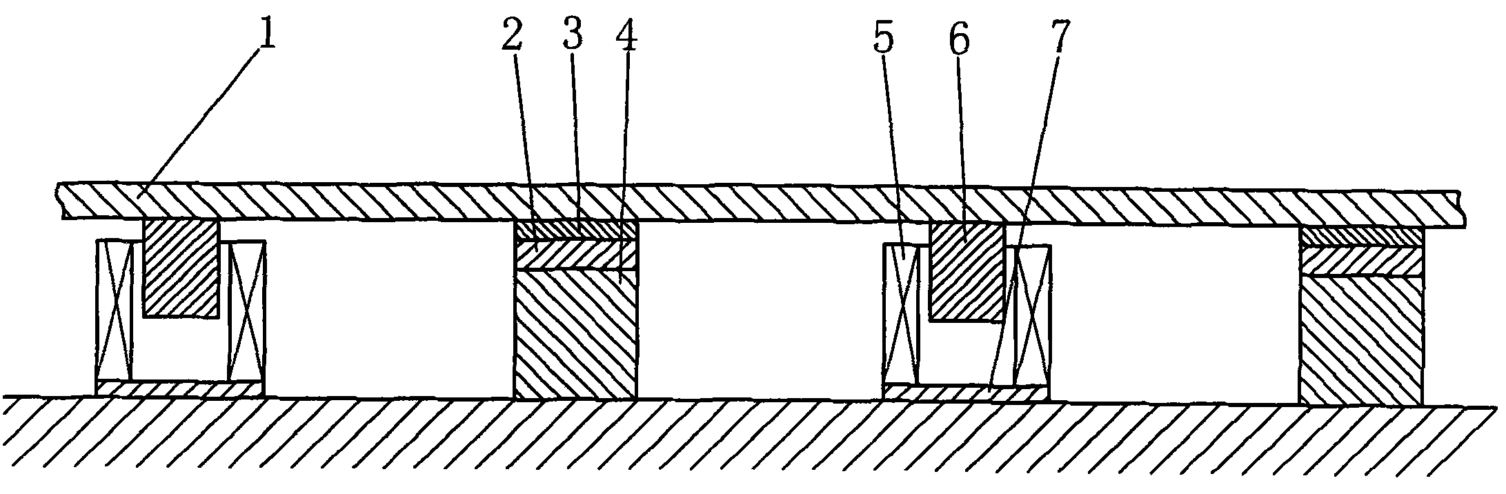
Figure 2
Abstract
Description
technical field
[0001] The invention relates to a rail car guide rail, in particular to a power generation guide rail. Background technique
[0002] Existing guide rails (steel rails) cannot be made absolutely rigid, and more steel materials are needed to make them very rigid, and the laying cost is greater, so the cost is doubled. In fact, the guide rail has a certain degree of elastic deformation (in practice, it can be observed with the naked eye), which can play a role in buffering and reducing vibration, and can increase the contact area between the wheel edge and the side of the guide rail, thereby greatly reducing the risk of derailment, and is beneficial to driving stability. Security can be beneficial. When the rail car is running on the guide rail (steel rail), the place where the guide rail is crushed by the wheels will sag and deform due to the action of gravity, and the sag deformation between the adjacent sleepers of the guide rail is relatively large, the mos...
Examples
Embodiment
[0011] Example: such as figure 1 As shown, the support 4 is fixed on the roadbed, the piezoelectric body 2 is connected on the top of the support 4, and the insulating pad 3 is placed on the upper end surface of the piezoelectric body 2, and the support 4, the piezoelectric body 2, and the insulating pad 3 form a piezoelectric sleeper. The guide rail 1 is placed on the upper end surface of the insulating pad 3 and fixed with the support 4; a certain distance away from the piezoelectric sleeper along the road length direction, the non-magnetic block 7 is connected under the guide rail 1, and the magnetic block 6 is connected under the non-magnetic block 7 , the coil 5 is sleeved outside the magnetic block 6 with a gap, the lower end surface of the coil 5 is fixed on the roadbed, the coil 5, the magnetic block 6, and the non-magnetic block 7 form an induction generating unit; the piezoelectric sleeper and the induction generating unit are along the guide rail 1 are arranged alte...