
All-terrain SUV (sports utility vehicle)
An off-road vehicle and all-terrain technology, applied in the field of all-terrain off-road vehicles and off-road vehicles, can solve the problems of inability to drive on complex terrain, increasing displacement, and dragging the bottom.
Patent Information
- Authority / Receiving Office
- CN · China
- Patent Type
- Applications(China)
- Current Assignee / Owner
- Publication Date
- 2017-11-07
- Estimated Expiration
- Not applicable · inactive patent
Smart Images
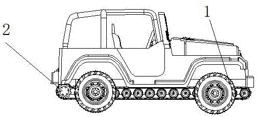
Figure 1 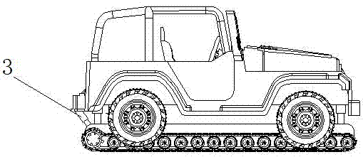
Figure 2 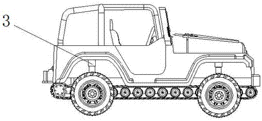
Figure 3
Abstract
Description
technical field
[0001] The invention relates to an off-road vehicle, in particular to an all-terrain off-road vehicle, belonging to the technical field of automobiles. Background technique
[0002] There are two types of vehicles or military vehicles on the market, tire and crawler. Tire-type vehicles can run at high speeds, but cannot drive on complex terrains. For example, snow chains need to be installed when encountering snow; while crawler-type vehicles are suitable for various complex terrains, but the driving speed is too low. Existing off-road vehicles have adopted methods such as enlarging tires, enlarging displacement, and heightening chassis in order to improve off-road capability, but it will drag the bottom in desert or gravel terrain, which is inconvenient. Contents of the invention
[0003] The object of the present invention is to provide an all-terrain off-road vehicle, which can change the driving mode of the vehicle and improve the maneuverability of th...
Examples
Embodiment 1
[0022] refer to figure 1 , figure 2 , Figure 5 , Figure 6 , Figure 7 and Figure 8 , a kind of all-terrain off-road vehicle, comprises vehicle frame, engine 5 and traveling system, and traveling system comprises first traveling device 2 and second traveling device 1; First traveling device 2 comprises chassis frame, a plurality of rollers 13 and is arranged on chassis Two belt assemblies below the frame, the belt assembly includes a driving wheel 10, a plurality of road wheels 11, a lifting wheel 6 and a connecting belt, the driving wheel 10 and the lifting wheel 6 are arranged at both ends of the chassis frame, and the lifting wheel 6 is connected to the lifting mechanism 4. The connecting belt connects the driving wheel 10, the load wheel 11 and the lifting wheel 6, and the roller 13 is located between the two belt assemblies and is arranged under the chassis frame; the second traveling device 1 includes walking tires 9 arranged at both ends of the frame, and the eng...
Embodiment 2
[0028] The difference with embodiment 1 is: refer to image 3 and Figure 4 The lifting device 3 is arranged on the second travel device 1 .