
Direct magnetic suspension permanent magnet linear synchronous motor for numerical control feeding platform
A magnetic levitation and motor technology, applied in the field of motors, can solve problems such as poor effect, poor stability and reliability, and complex structure, and achieve the effect of easy adjustment, simple magnetic circuit structure, and difficult adjustment of the air gap magnetic field
Patent Information
- Authority / Receiving Office
- CN · China
- Patent Type
- Patents(China)
- Current Assignee / Owner
- Publication Date
- 2012-05-30
- Estimated Expiration
- Not applicable · inactive patent
Smart Images
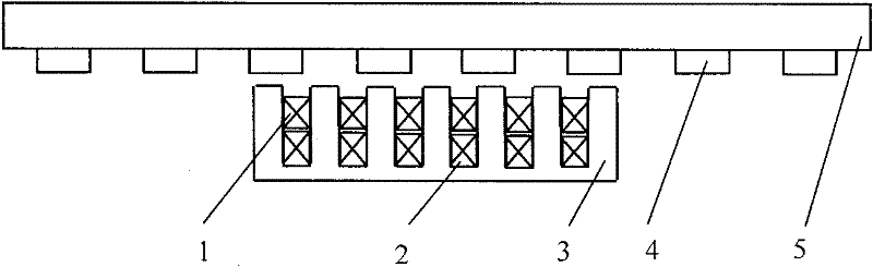
Figure 1 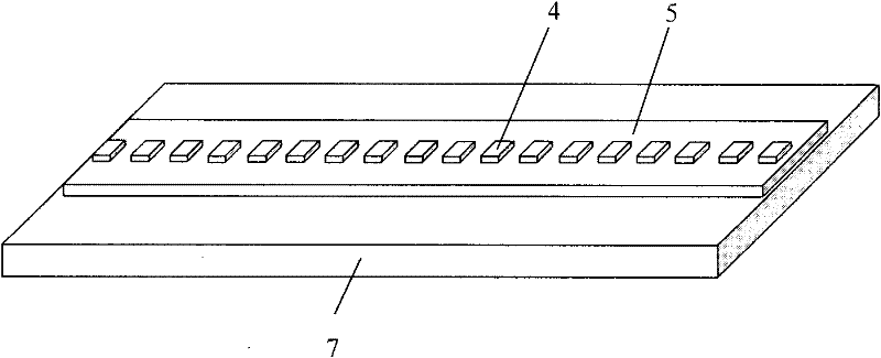
Figure 2 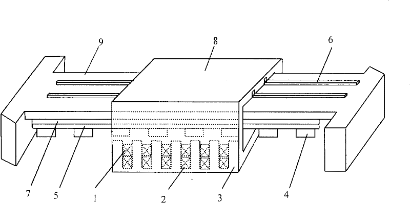
Figure 3
Abstract
Description
technical field
[0001] The invention relates to a direct magnetic levitation permanent magnet linear synchronous motor used for a numerical control feed platform, in particular to a magnetic levitation permanent magnet linear synchronous motor used for a frictionless direct feed servo system of a numerical control machine tool, belonging to the technical field of electric motors . Background technique
[0002] The friction resistance in CNC machine tool processing, especially the nonlinear friction at low speed will inevitably affect the accuracy of the servo system, causing the feed system to crawl and cause the reverse dead zone. Friction is one of the causes of thermal deformation of CNC machine tools and an important factor affecting machining accuracy. In addition, friction is also a factor that causes wear and noise, and good lubrication is required to increase the life of the machine tool. Therefore, how to effectively reduce or eliminate friction has become a techn...
Examples
Embodiment Construction
[0023] Below in conjunction with accompanying drawing, the present invention will be further described:
[0024] Such as figure 1 and 2 As shown, the present invention provides a direct magnetic levitation permanent magnet linear synchronous motor for a digitally controlled feed platform, comprising a stator core 5 and a mover core 3 that moves along the stator core 5 during use, and the stator core 5 is arranged on a non-magnetic on the motor base 7. The permanent magnet 4 is arranged on the side of the stator core 5 facing the mover core 3 .
[0025] Two sets of electrically independent windings are arranged in the mover core 3, one of which is the thrust winding 2 for generating electromagnetic thrust, and the other is the levitation winding 1 for adjusting the magnetic levitation force; the thrust winding 2 When in use, the mover core 3 can move relative to the stator core 5, and the suspension winding 1 can make the mover core 3 suspend under the stator core 5, so that...