
Energy feedback type power unit cascaded high voltage frequency converter
A high-voltage inverter and power unit technology, applied in the direction of converting AC power input into AC power output, irreversible DC power input into AC power output, and output power conversion devices, etc. Coordinated action, bulky and other problems, to achieve the effect of reducing volume and weight, perfect and feasible plan, and eliminating low-frequency pulsation
Patent Information
- Authority / Receiving Office
- CN · China
- Patent Type
- Patents(China)
- Current Assignee / Owner
- Publication Date
- 2013-10-30
- Estimated Expiration
- Not applicable · inactive patent
Smart Images
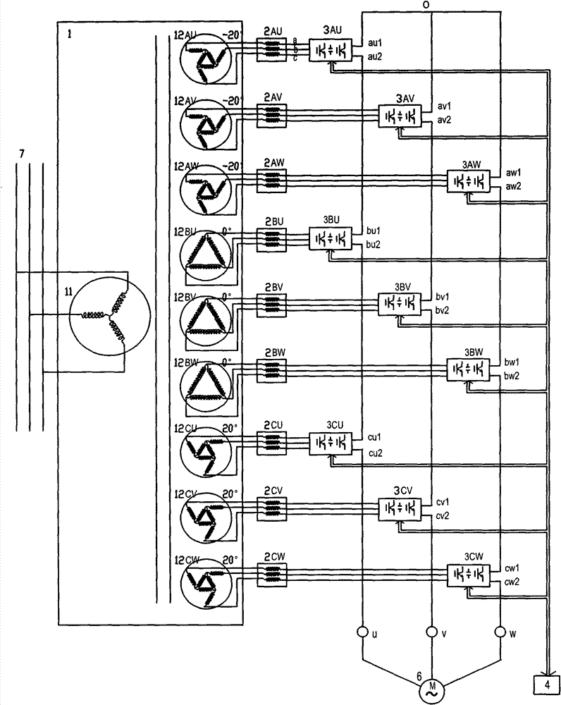
Figure 1 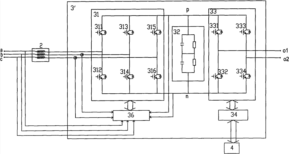
Figure 2 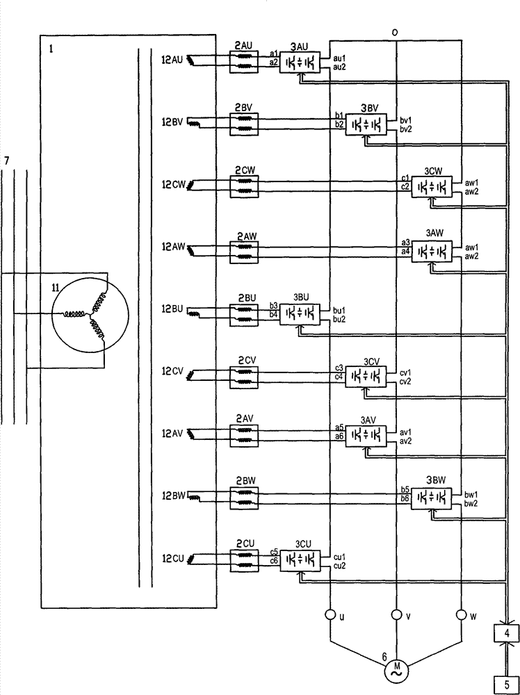
Figure 3
Abstract
Description
technical field
[0001] The invention relates to power electronics technology, in particular to an energy feedback type power unit series high-voltage frequency converter. Background technique
[0002] In recent years, industrial energy saving and consumption reduction have gradually received widespread attention. As an important power-consuming equipment, high-voltage motors are also more and more adopted frequency conversion speed regulation to achieve economical operation.
[0003] In the field of high-voltage inverters, since Peter W. Hammond proposed the unit-series high-voltage inverter in 1995, this method of realizing high-voltage power conversion through low-voltage power conversion technology is due to its good output voltage waveform, low input harmonic current, and low cost. Low cost and easy maintenance have become the mainstream technology of high-voltage inverters. Many high-voltage inverter manufacturers at home and abroad have launched products based on this...
Examples
Embodiment Construction
[0055] The product of the present invention will be further described in detail below in conjunction with the accompanying drawings and embodiments of the present invention.
[0056] Here, an energy feedback type high-voltage inverter with three power units connected in series for each phase is used as an example for illustration, as shown in Figure 2A Shown is the schematic diagram of its main circuit wiring, Figure 2B It is the circuit composition of the power unit. The shown high-voltage frequency converter includes a main transformer 1 , 9 reactors (such as 2AU), 9 power units (such as 3AU), a main controller 4 and a sensor circuit 5 .
[0057] The main transformer 1 shown is a three-phase multi-secondary winding transformer, and its primary winding 11 is connected to the three-phase high-voltage power grid 7, and all the secondary windings (such as 12AU) are used as a group, including the same three circuits (such as 12AU / 12BV / 12CW ), each secondary winding (such as 1...