
High-rise fire safety escape device with escape hatch
An escape cabin and escape device technology, which is applied in the field of high-rise escape, can solve problems such as limited application range, few escape opportunities, and poor safety, and achieve the effects of good safety, saving escape time, and reasonable structure
Patent Information
- Authority / Receiving Office
- CN · China
- Patent Type
- Patents(China)
- Current Assignee / Owner
- Publication Date
- 2012-08-22
Smart Images
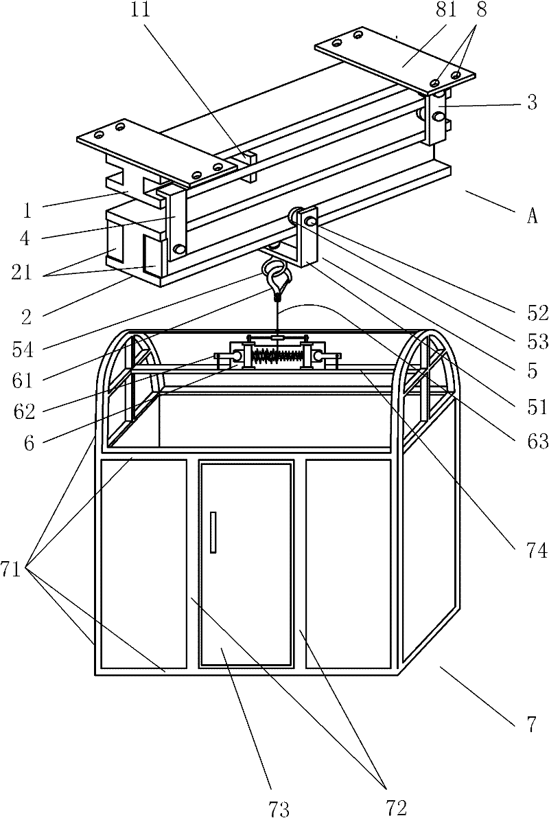
Figure 1 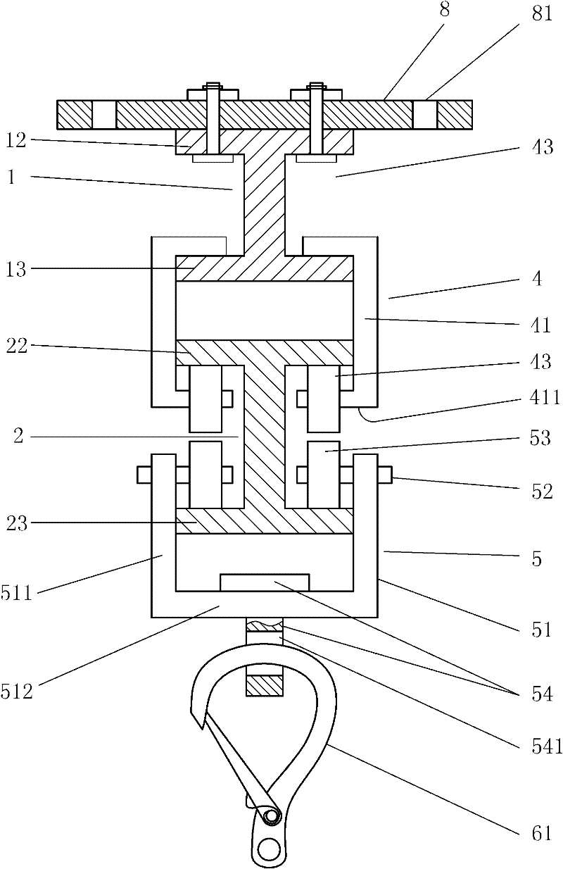
Figure 2 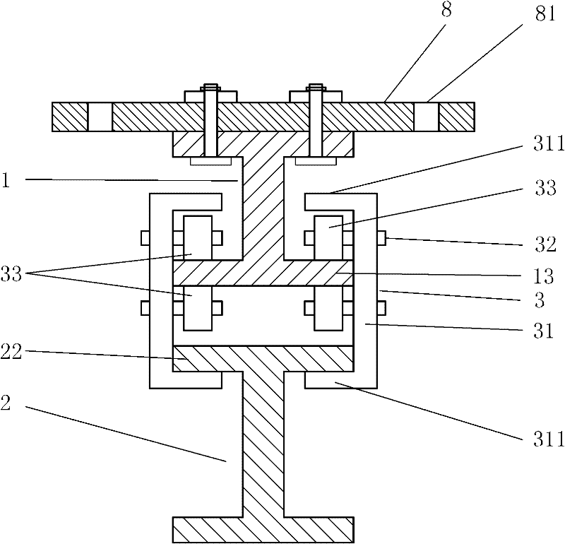
Figure 3
Abstract
Description
technical field
[0001] The invention belongs to the technical field of high-rise escape, in particular to a high-rise fire safety escape device with an escape cabin. Background technique
[0002] With the application of building materials in the construction industry, the development of construction technology and the increase of population, the land use area decreases, and the floors used by people for office or residence are getting higher and higher. However, in recent years, fires in high-rise buildings at home and abroad Occurs constantly, due to the lack of escape equipment, every time a fire is accompanied by a large number of people's death, serious injury or disability, although there are also some high-rise escape equipment that have patent applications or are put into the market, the disadvantages are: first, poor safety, resulting in a wide range of applications Restricted, can not be popularized; The 2nd, mostly are single-person escape appliances, when there ar...
Examples
Embodiment Construction
[0025] Below in conjunction with accompanying drawing, the present invention will be further described with specific embodiment, see Figure 1-4 : a high-rise fire safety escape device with an escape cabin, including a rope retractable mechanism 6, the upper part of the rope retractable mechanism 6 is connected to the telescopic suspension mechanism A, and the lower part of the rope retractable mechanism 6 is connected to the upper suspension of the escape cabin 7 On position 74, the telescopic suspension mechanism A is: there are more than two I-beams 1, 2 arranged in parallel up and down, and the upper horizontal plate 12 of the I-beam 1 on the upper side is provided with a fixed plate 8, adjacent Two I-beams 1 and 2 are slidably connected by a sliding mechanism, and a sliding suspension frame 5 is set on the lower side cross plate 23 of the lowermost I-beam 2, and the rope extension end of the rope retracting mechanism 6 is connected to the slide by a hook 61. On the suspen...