
Tool capable of applying pressure to carry out electron beam auxiliary heat action connection
A technique of applying pressure and electron beam, which is used in electron beam welding equipment, auxiliary welding equipment, auxiliary devices, etc.
Patent Information
- Authority / Receiving Office
- CN · China
- Patent Type
- Patents(China)
- Current Assignee / Owner
- Publication Date
- 2014-11-12
- Estimated Expiration
- Not applicable · inactive patent
Smart Images
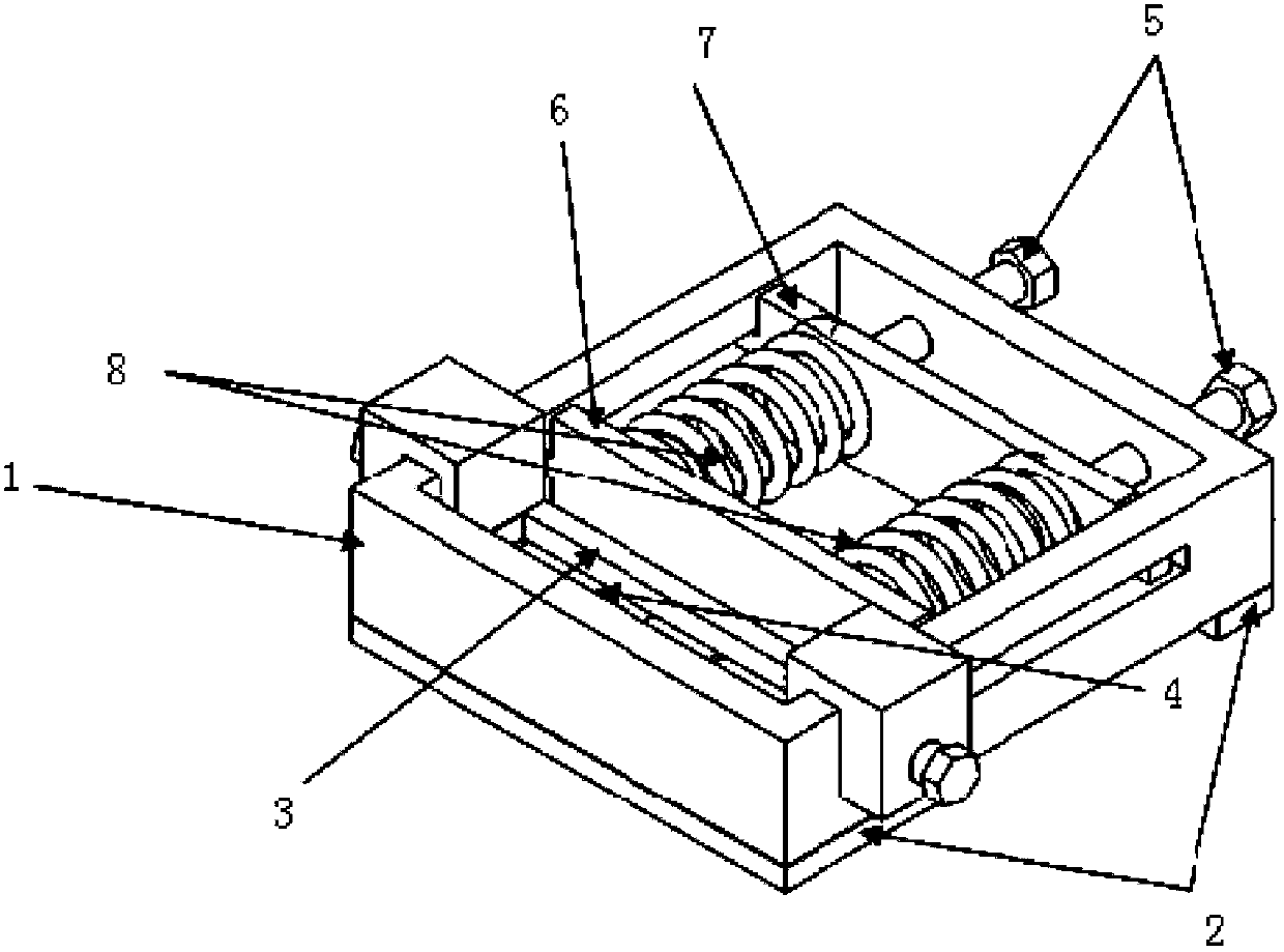
Figure 1 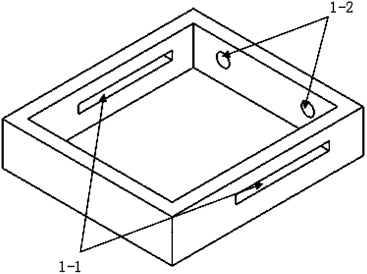
Figure 2 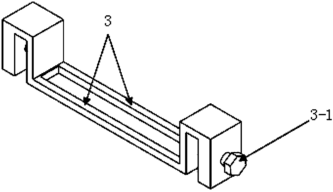
Figure 3
Abstract
Description
technical field
[0001] The invention relates to a welding fixture for an electron beam assisted heat source action connection method, which belongs to the field of welding auxiliary tools. Background technique
[0002] For some materials, such as composite materials, it is difficult to achieve excellent connection effects by traditional fusion welding methods, which will cause serious metal burning and interface reactions. In addition to heating the parts, it is also necessary to heat the weldment as a whole, which will exert additional heat on the base metal of the weldment and affect the overall performance of the base metal. Therefore, it is considered to only carry out local thermal action connection on the welded joints, without welding and heating the base metal as a whole. This requires the use of high-energy-density welding methods with small heat source action areas, such as laser welding and electron beam welding. However, the existing high-energy welding equipmen...
Examples
specific Embodiment approach 1
[0019] Embodiment 1: A tool capable of applying pressure for electron beam assisted thermal connection in this embodiment is composed of a clamp shell 1, a clamp base 2, a vertical fixing device and a horizontal fixing device, wherein the clamp shell 1 is fixedly connected On the fixture base 2, two opposite side walls of the fixture shell 1 are provided with sliding guide grooves 1-1, and the rear wall of the fixture shell 1 is provided with limiting holes 1-2, and the vertical fixing device is arranged on the fixture shell 1 The internal front end, the vertical fixing device is composed of a vertical fixing rod 3 and a bottom backing plate 4, the two ends of the vertical fixing rod 3 are engaged with the two side walls of the fixture shell 1 by fastening screws 3-1, and the bottom backing plate 4 is set Directly below the vertical fixing rod 3, wherein, the bottom backing plate 4 is provided with two raised fixing bars 4-1 and is opposite to the vertical fixing rod 3. The fi...
specific Embodiment approach 2
[0030] Embodiment 2: This embodiment is different from Embodiment 1 in that: the main material of the fixture shell 1 is stainless steel without ferromagnetism. Other steps and parameters are the same as those in Embodiment 1.
specific Embodiment approach 3
[0031] Embodiment 3: This embodiment differs from Embodiment 1 or Embodiment 2 in that the clamp base 2 is made of non-ferromagnetic 6061 aluminum alloy. Other steps and parameters are the same as those in Embodiment 1 or Embodiment 2.