
Far-infrared electric heating air conditioning heating module
A far-infrared and electric heating technology, applied in the direction of electric heating devices, ohmic resistance heating, electrical components, etc., can solve the problems of high energy consumption, limited heat absorption, and reduced indoor humidity, and achieve high heating efficiency
Patent Information
- Authority / Receiving Office
- CN · China
- Patent Type
- Patents(China)
- Current Assignee / Owner
- Publication Date
- 2015-12-16
Smart Images
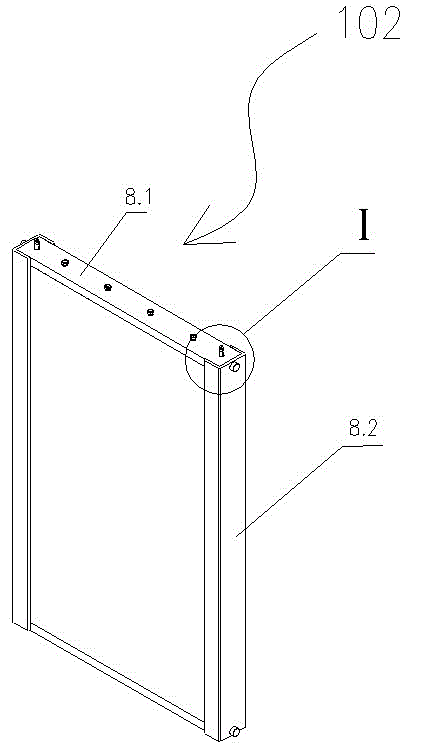
Figure 1 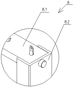
Figure 2 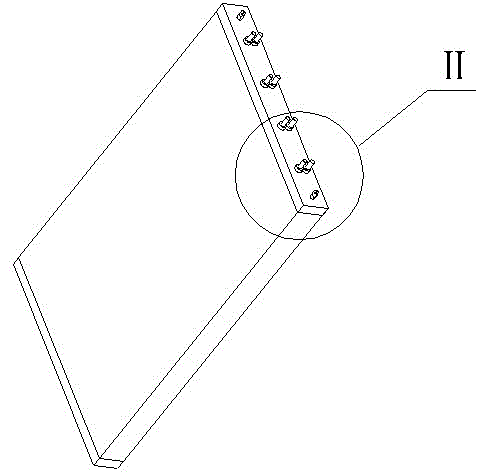
Figure 3
Abstract
Description
technical field
[0001] The invention relates to a heating module, in particular to a heating module used in a far-infrared electric heating air conditioner, and belongs to the technical field of air conditioning. Background technique
[0002] At present, people generally need to use air conditioners to heat and heat the room in winter, especially in the northern region, every household needs to be heated to keep out the cold, and the cost of heating for each household is as high as thousands of yuan every year. It is to use coal to heat to generate steam. The use of fossil fuels not only pollutes the environment, is not conducive to energy conservation and environmental protection, but also tends to generate more losses during the transmission of heating. For conventional air conditioners, there are two main heating methods:
[0003] The first heating principle is like that of some electric heaters. It is through the heating of the electric heating tube that the electric e...
Examples
Embodiment Construction
[0034] see Figure 1~11 , a far-infrared electric heating air-conditioning heating module related to the present invention, the module includes a heating module 102; the heating module 102 is formed by stacking a heating chip 101 and a heat sink 5 at intervals, when stacked, the heating chip 101 and the heat dissipation The specific number of chips 5 can be determined by the rated power when installed;
[0035] The heating chip 101 includes two substrates 1 as the upper surface layer and the lower surface layer, and two conductive sheets 3 that are arranged between the two substrates 1 and serve as electrodes, and are arranged between the two substrates 1. There is an adhesive layer 4 for connecting the two substrates 1 and the conductive sheet 3, and the upper surface of the substrate 1 as the lower surface layer is coated with a conductive ink layer 2 (such as Figure 8 As shown), the conductive ink layer 2 can be set into a linear structure or a planar structure according ...