
Exhaust manifold circulation area self-regulation type engine system
An engine system and exhaust branch pipe technology, which is applied in combustion engines, machines/engines, internal combustion piston engines, etc., can solve the problems of complex structure of the supercharging system, and achieve the effect of simple structure and reasonable design.
Patent Information
- Authority / Receiving Office
- CN · China
- Patent Type
- Applications(China)
- Current Assignee / Owner
- Publication Date
- 2013-12-18
- Estimated Expiration
- Not applicable · inactive patent
Smart Images
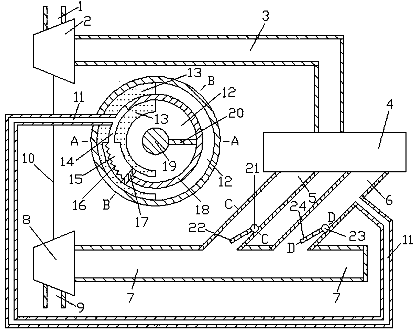
Figure 1 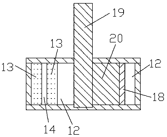
Figure 2 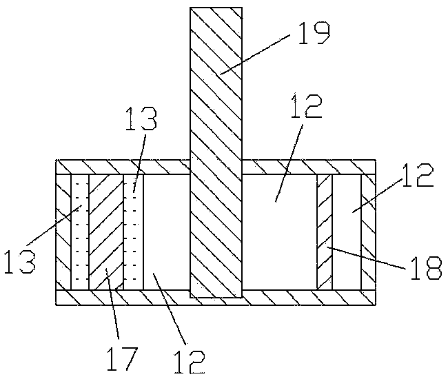
Figure 3
Abstract
Description
technical field
[0001] The invention relates to a turbocharging system in the technical field of mechanical design, in particular to a self-adjusting exhaust branch pipe flow area engine system. Background technique
[0002] With the development of society and the improvement of environmental protection requirements, the application of engine supercharging technology is becoming more and more extensive. Most of the engines with medium and high power adopt turbocharging technology to improve power and reduce fuel consumption. The two basic types of turbocharging systems are constant pressure supercharging system and pulse supercharging system. Constant pressure supercharging system, each cylinder shares an exhaust pipe with a large volume, the structure of the exhaust pipe system is relatively simple, the pressure in the exhaust pipe is basically kept constant, the pressure is only related to the load and speed of the engine, different cylinder numbers The supercharging syst...
Examples
Embodiment
[0018] Such as Figure 1 to Figure 6 Shown, the present invention comprises compressor intake pipe 1, compressor 2, engine intake pipe 3, engine 4, first exhaust branch pipe 5, second exhaust branch pipe 6, exhaust pipe 7, turbine 8, turbine exhaust pipe 9. Connecting shaft 10, connecting pipe 11, volume cavity 12, fixed body 13, first through pipe 14, second through pipe 15, elastic member 16, partition 17, rotating body 18, first rotating shaft 19, connecting plate 20. The second rotating shaft 21, the first rotating plate 22, the third rotating shaft 23, the second rotating plate 24 and the chain 25, the air inlet and outlet of the compressor 2 are respectively connected with the air outlet of the compressor inlet pipe 1 and the engine inlet pipe 3 The intake port of the engine 4 is connected with the exhaust port of the engine intake pipe 3, and the air intake port of the first exhaust branch pipe 5 and the air intake port of the second exhaust branch pipe 6 are connected ...