
Multielement linear array high-speed heat distribution imaging detector
An imaging detector and heat distribution technology, applied in electric radiation detectors, radiation pyrometry, instruments, etc., can solve the problems of limited single-probe detection parts, high price, complex multi-probe technology, etc., and achieve pyroelectric effect time Small constant, wide field of view, and high light-gathering efficiency
Patent Information
- Authority / Receiving Office
- CN · China
- Patent Type
- Applications(China)
- Current Assignee / Owner
- Publication Date
- 2014-03-12
- Estimated Expiration
- Not applicable · inactive patent
Smart Images
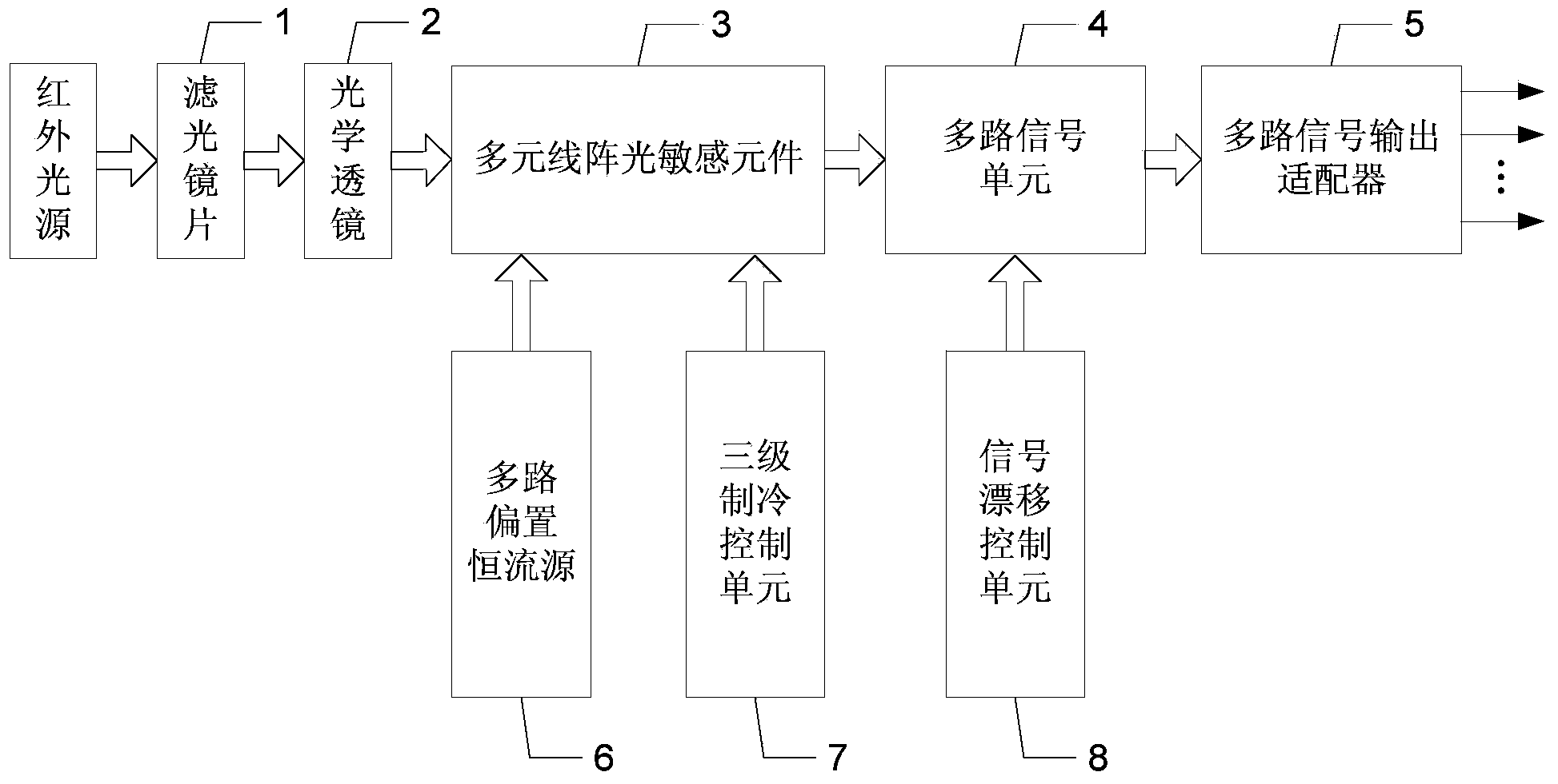
Figure 1 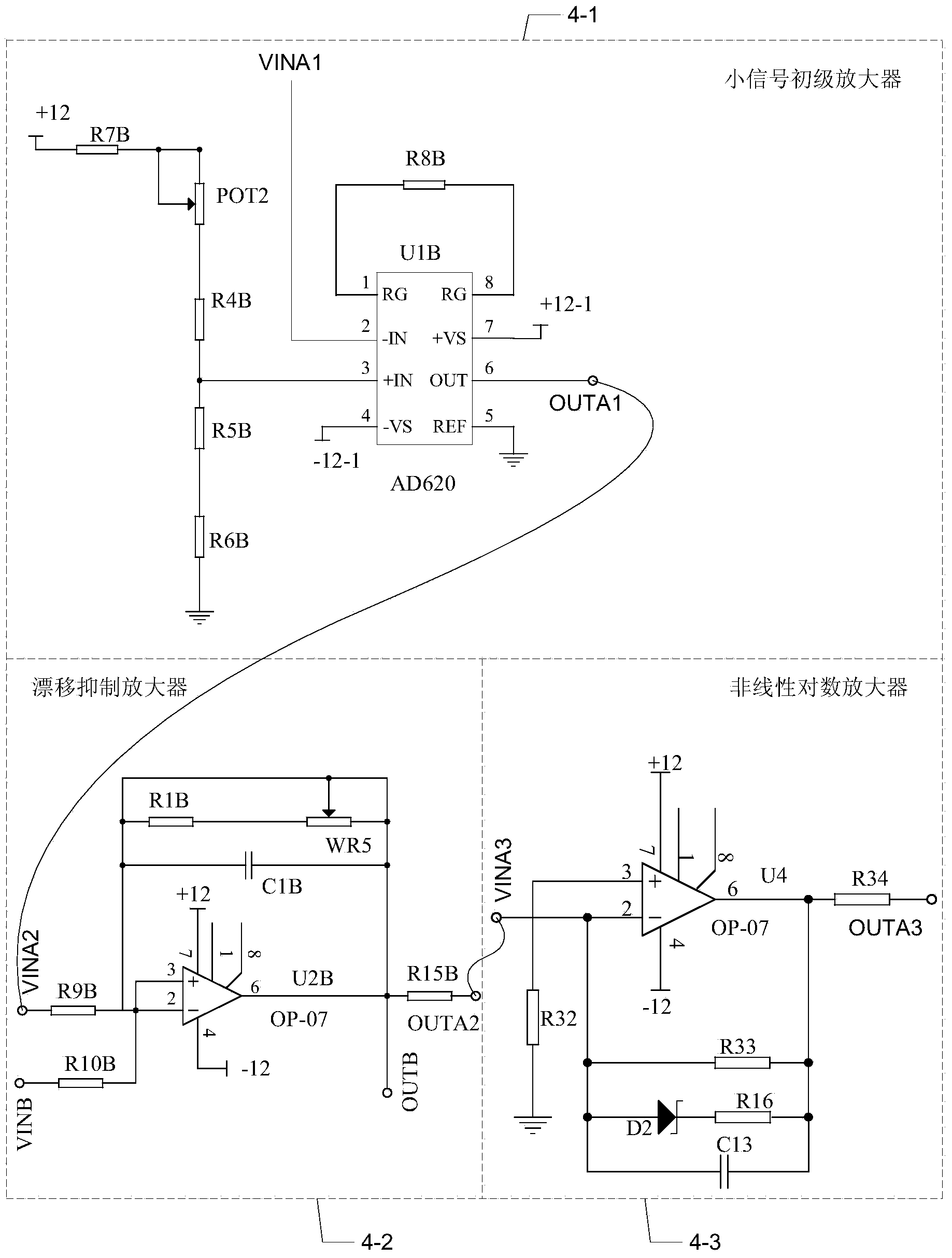
Figure 2 
Figure 3
Abstract
Description
technical field
[0001] The invention relates to a heating fault detection device, which belongs to the technical field of safety detection of high-speed railway vehicles. Background technique
[0002] At present, the detection of heating faults of high-speed railway vehicles or high-speed moving objects is still limited to the line track scanning method at home and abroad. The range of objects that can be scanned is a light band with a width of 40mm at 1m, and heat points outside the light band cannot be detected. For detection, there are also attempts to use multiple detection probes at the same time, but the scanning band cannot continuously form a thermal distribution map in the area, and it greatly increases the complexity and maintainability of the equipment. Even though general-purpose thermal imaging equipment can combine thermal distribution with optical photography to visually display the thermal distribution of the measured object, it can only accurately detect sta...
Examples
specific Embodiment approach 1
[0019] Specific implementation mode one: the following combination Figure 1 to Figure 3 Describe this embodiment, the multi-element linear array high-speed thermal distribution imaging detector described in this embodiment includes a filter lens 1, an optical lens 2, a multi-element linear array photosensitive element 3, a multi-channel signal amplification unit 4, and a multi-channel signal output Adapter 5, multi-channel bias constant current source 6, three-stage refrigeration control unit 7 and signal drift control unit 8;
[0020] The high-speed moving object to be measured reflects the mixed beam of visible light and infrared light;
[0021] After the mixed beam of visible light and infrared light is filtered out by the filter lens 1 to filter out the visible light, the output infrared beam is incident on the photosensitive surface of the multi-element linear array photosensitive element 3 through the optical lens 2;
[0022] The electrical signal output end of the mul...
specific Embodiment approach 2
[0030] Specific embodiment two: this embodiment will further explain embodiment one, the optical filter lens 1 is a visible light bandpass filter zinc sulfide lens, the optical lens 2 is a wide-field double-spherical infrared harmonic diffraction lens, and the mixed beam of visible light and infrared light is incident To the visible light band-pass filter zinc sulfide lens, the visible light band-pass filter zinc sulfide lens outputs infrared beams, and enters the wide-field double-spherical infrared harmonic diffraction lens, and the wide-field double-spherical infrared harmonic diffraction lens outputs the surface of the high-speed moving object to be measured The temperature image is focused on the photosensitive surface of the multi-element linear array photosensitive element 3 .
[0031] The high-speed moving object to be tested is easy to generate heat. The higher the temperature of the high-speed moving object to be measured, the stronger the intensity of the infrared li...
specific Embodiment approach 3
[0033] Specific implementation mode three: the following combination figure 2 and Figure 5 Describe this embodiment mode, this embodiment mode will further illustrate Embodiment 1, multi-channel signal amplifying unit 4 comprises small-signal primary amplifier 4-1, drift suppressing amplifier 4-2 and nonlinear logarithmic amplifier 4-3, small-signal primary amplifier The output terminal of 4-1 is connected with the input terminal of drift suppression amplifier 4-2, and the output terminal of drift suppression amplifier 4-2 is connected with the input terminal of nonlinear logarithmic amplifier 4-3.
[0034] Small-signal primary amplifier 4-1 adopts AD620 operational amplifier as the core chip.
[0035] The output terminal OUTA3 of the nonlinear logarithmic amplifier 4-3 is used as the signal output of the detector, and is connected to the host computer for signal acquisition.
[0036] The multi-channel signal amplifying unit 4 amplifies the output signal of the multi-eleme...