
Hydraulic damping type wind heating system
A hydraulic damping and heating technology, which is applied in the direction of heating system, wind engine, wind motor combination, etc., can solve the problems of low wind energy utilization rate and poor system stability, and achieve excellent heating effect, large pressure loss, and small loss effect
Patent Information
- Authority / Receiving Office
- CN · China
- Patent Type
- Applications(China)
- Current Assignee / Owner
- Publication Date
- 2015-01-07
- Estimated Expiration
- Not applicable · inactive patent
Smart Images
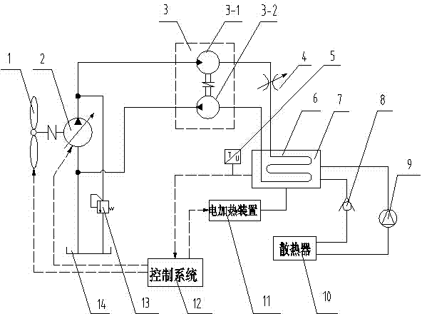
Figure 1
Abstract
Description
technical field
[0001] The invention relates to a wind heating system, in particular to a hydraulic damping wind heating system. Background technique
[0002] At present, the heating in northern my country mainly relies on the combustion of fossil fuels, which has brought about further deterioration of the environment, and the smog phenomenon has become more and more serious. In addition, the call for heating in winter in southern my country has also intensified, and the search for clean and pollution-free new energy heating has become a major problem that people urgently need to solve. As a green and environmentally friendly clean renewable energy, wind energy can be used in various forms, but it is mainly used for wind power generation and water pumping at present, and there are few studies on wind heating. Among them, the utilization rate of wind energy for wind heating is higher than that of wind power generation and wind power water extraction, and its realization form...
Examples
Embodiment Construction
[0019] The present invention will be described in further detail below in conjunction with the accompanying drawings.
[0020] A hydraulic damping type wind heating system of the present invention such as figure 1 As shown, it mainly includes: wind turbine 1, variable pump 2, double pump unit 3, hydraulic motor 3-1, hydraulic pump 3-2, throttle valve 4, temperature sensor 5, heat exchange tube 6, heat preservation water tank 7, Check valve 8, water inlet pump 9, radiator 10, electric heating device 11, control system 12, overflow valve 13, oil tank 14.
[0021] The wind turbine 1 is connected to the variable pump 2 through a coupling, the oil inlet of the variable pump 2 is connected to the oil tank 14, and the oil outlet of the variable pump 2 is connected to the oil inlet of the hydraulic motor 3-1 in the double pump group 3. A relief valve 13 is bypassed between the variable pump 2 and the hydraulic motor 3-1, and the oil outlet of the relief valve 13 is connected to the o...