
Pneumatic blanking mechanism
An air chamber and discharge port technology is applied in the field of material collection and discharge equipment, which can solve the problems of increasing production costs, high production difficulties, and high equipment failure rates, reducing production and use costs, low space requirements, and wide application range. Effect
Patent Information
- Authority / Receiving Office
- CN · China
- Patent Type
- Patents(China)
- Current Assignee / Owner
- Publication Date
- 2017-04-05
Smart Images
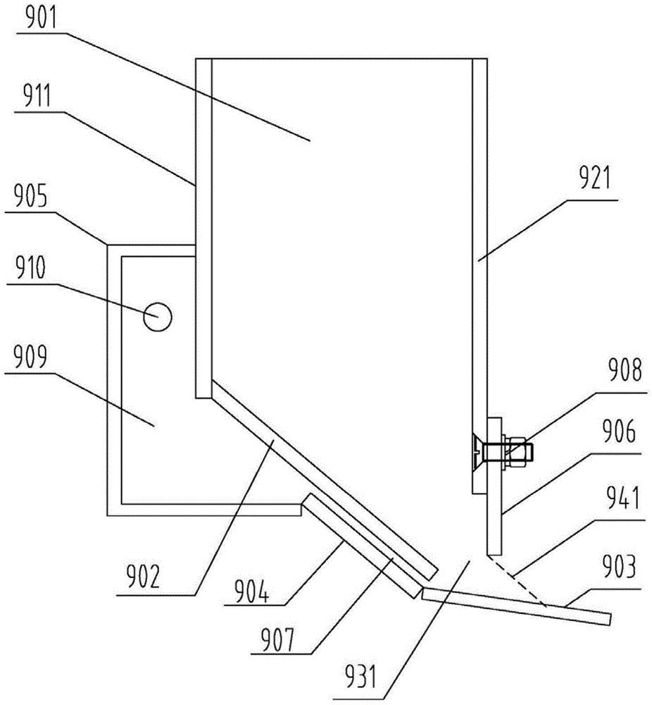
Figure 1
Abstract
Description
technical field
[0001] The invention belongs to the field of material collection and discharge equipment, and in particular relates to a pneumatic unloading device for solid particle materials. Background technique
[0002] my country controls SO 2 and NO x The emission task is very heavy, and the emission standards are getting higher and higher. At present, most of the waste gas purification adopts wet technology, which consumes a lot of water resources and causes secondary pollution, and cannot desulfurize and denitrify at the same time, especially in the coal-rich northern my country. In areas short of water, water resources restrict economic construction and development.
[0003] Activated carbon flue gas purification technology is a recyclable dry flue gas purification technology. At a temperature of 80-150 ° C, through the adsorption and catalysis of activated carbon, the sulfur dioxide, oxygen and water in the exhaust gas are converted into sulfuric acid adsorbed on ...
Examples
Embodiment 1
[0019] Such as figure 1 As shown, the pneumatic unloading mechanism includes a receiving channel 901, wherein the receiving channel is a vertical material channel with a square cross section, which includes long side walls and wide side walls, and the square section aspect ratio of the receiving channel is 1.5 times or more, for example 6m×0.3m. An inclined bottom plate 902 is provided at the opening of the lower end of the material receiving channel 901, and the upper end of the bottom plate 902 is closely connected with a long side wall of the material receiving channel, and the bottom plate 902 is inclined to the other long side wall of the material receiving channel. The direction is set, and the lower end of the bottom plate 902 together with the corresponding long side wall of the receiving channel and the two wide side walls of the receiving channel form the discharge port 931 . In another solution, the bottom plate 902 can be directly formed by inclining a side wall o...
Embodiment 2
[0025] The structure of this pneumatic blanking mechanism is the same as that of Embodiment 1 in respect of the gas channel 907, the base plate 902 and the regulating plate 906. The different structure mainly lies in the aerodynamic structure, especially the gas channel is directly replaced by the long and narrow air outlet of the aerodynamic structure. In this example, a compressed gas chamber is provided below the base plate 902, and a compressed gas chamber may also be provided on the side wall of the receiving channel. The compressed gas chamber has a compressed gas inlet, and the compressed gas chamber is close to the base plate. The position of the lower end is provided with a long slit with the same length as the lower end of the bottom plate, or the gas outlet part of the compressed gas chamber extends below the bottom plate and forms a long slit with the same length as the lower end of the bottom plate at the lower end of the bottom plate. The slit is the compressed g...
Embodiment 3
[0027] The pneumatic unloading mechanism includes a material receiving channel 901, wherein the material receiving channel is a vertical material channel with an elliptical cross-section, and the length-to-diameter ratio of the elliptical cross-section of the material receiving channel is more than 1.5 times. An inclined bottom plate 902 is provided at the opening of the lower end of the receiving channel 901. The upper end of the bottom plate 902 is closely connected with the side wall in the longer direction of the receiving channel, and the bottom plate 902 is inclined along the other longer side wall of the receiving channel. The direction is set, and the lower end of the bottom plate 902 and the opening of the receiving passage form the discharge opening 931. In another solution, the bottom plate 902 can be directly inclined from a side wall of the receiving channel to form a similar structure.
[0028] An adjustment plate 906 is provided on the side wall of the receiving...