
A Shockless Adaptive Trigger Ignition Device Utilizing Laminar Plasma System
A laminar plasma and ignition device technology, which is applied in the ignition, plasma, combustion ignition and other directions using electric sparks, can solve the problems of high cost, low monomer power, low thermal efficiency, etc., and achieves good uniformity and fast heating speed. , the effect of uniform heat distribution
Patent Information
- Authority / Receiving Office
- CN · China
- Patent Type
- Patents(China)
- Current Assignee / Owner
- Publication Date
- 2019-12-13
Smart Images
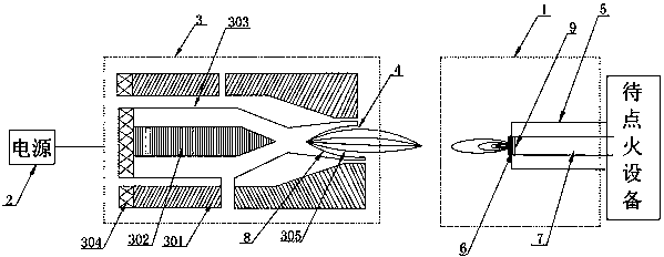
Figure 1
Abstract
Description
technical field
[0001] The invention relates to an ignition device, in particular to a non-impact self-adaptive trigger ignition device utilizing a laminar flow plasma system, and belongs to the technical field of ignition equipment. Background technique
[0002] Ignition devices are required to reliably ignite flames in boilers, burners, industrial furnaces, flares, gas relief systems, and many other applications. Existing ignition devices are mainly electric ignition, which uses high-voltage electric ignition, arc ignition and electric heating to ignite the flame. The ignition device is mainly composed of an electric ignition part and other auxiliary parts. The electric ignition part includes an electric ignition element and an electrode. The electric ignition element generates an electric spark through the electrode, ignites the combustible gas mixture, and forms a stable flame to complete the ignition. Task. However, the electrode part of the above-mentioned ignition d...
Examples
Embodiment 1
[0029] A non-impact adaptive trigger ignition device utilizing a laminar plasma system, comprising a laminar plasma system and an ignition nozzle 1, the laminar plasma system comprising a power supply 2, a laminar plasma generator 3 and a nozzle 4, the power supply 2 is connected to the layer Flow plasma generator 3, nozzle 4 is detachably connected with laminar flow plasma generator 3; Described ignition nozzle 1 is arranged on the equipment to be ignited, and ignition nozzle 1 comprises housing 5, ignition pole 6 and conduit 7, ignition pole 6 is arranged on the front end of the conduit 7, and the conduit 7 extends into the device to be ignited, and the housing 5 is arranged outside the ignition pole 6 and the conduit 7; the nozzle 4 coincides with the central axis of the ignition nozzle 1.
Embodiment 2
[0031] A non-impact adaptive trigger ignition device utilizing a laminar plasma system, comprising a laminar plasma system and an ignition nozzle 1, the laminar plasma system comprising a power supply 2, a laminar plasma generator 3 and a nozzle 4, the power supply 2 is connected to the layer Flow plasma generator 3, nozzle 4 is detachably connected with laminar flow plasma generator 3; Described ignition nozzle 1 is arranged on the equipment to be ignited, and ignition nozzle 1 comprises housing 5, ignition pole 6 and conduit 7, ignition pole 6 is arranged on the front end of the conduit 7, and the conduit 7 extends into the device to be ignited, and the housing 5 is arranged outside the ignition pole 6 and the conduit 7; the nozzle 4 coincides with the central axis of the ignition nozzle 1.
[0032] The laminar flow plasma generator 3 includes an anode structure 301, a cathode structure 302 and a multi-air film cooling device 303. The anode structure 301 is an anode structure...
Embodiment 3
[0034] A non-impact adaptive trigger ignition device utilizing a laminar plasma system, comprising a laminar plasma system and an ignition nozzle 1, the laminar plasma system comprising a power supply 2, a laminar plasma generator 3 and a nozzle 4, the power supply 2 is connected to the layer Flow plasma generator 3, nozzle 4 is detachably connected with laminar flow plasma generator 3; Described ignition nozzle 1 is arranged on the equipment to be ignited, and ignition nozzle 1 comprises housing 5, ignition pole 6 and conduit 7, ignition pole 6 is arranged on the front end of the conduit 7, and the conduit 7 extends into the device to be ignited, and the housing 5 is arranged outside the ignition pole 6 and the conduit 7; the nozzle 4 coincides with the central axis of the ignition nozzle 1.
[0035]The laminar flow plasma generator 3 includes an anode structure 301, a cathode structure 302 and a multi-air film cooling device 303. The anode structure 301 is an anode structure ...