
Paint removing method and paint removing equipment for surface of metal hanging rack
A metal and paint stripping technology, applied in chemical instruments and methods, cleaning methods and utensils, cleaning methods using liquids, etc., can solve problems such as environmental pollution, poor paint stripping effect, etc., to avoid polluting the soil, eliminating waste gas emissions, high efficiency effect
Patent Information
- Authority / Receiving Office
- CN · China
- Current Assignee / Owner
- Publication Date
- 2017-05-10
Smart Images
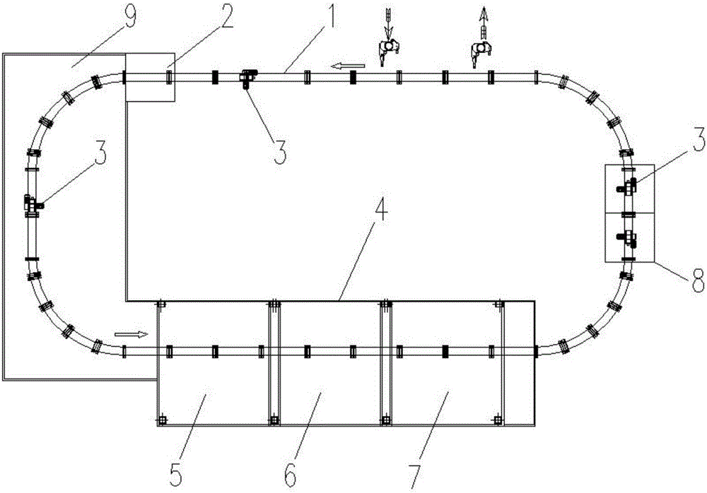
Figure 1 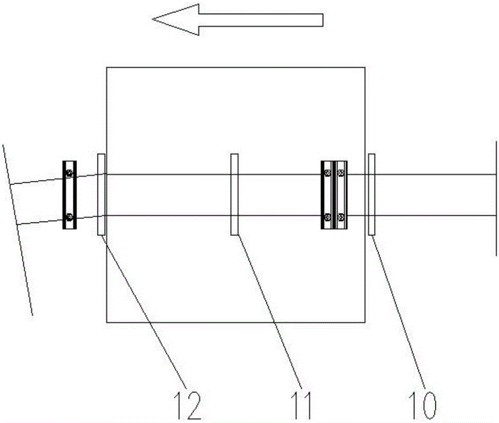
Figure 2 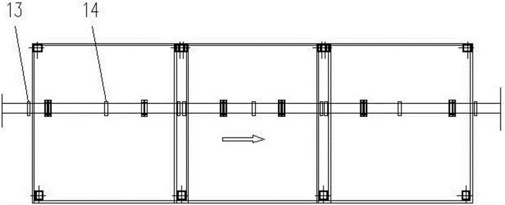
Figure 3
Abstract
Description
Technical field
[0001] The invention relates to the field of paint removal on metal surfaces, in particular to a method and equipment for removing paint on the surface of a metal hanger. Background technique
[0002] With the large-scale development of the industry, in the manufacturing fields of home appliances, automobiles, and electronic products, in order to ensure the quality standards and the aesthetics of the viewing parts, the coating process is more and more widely used. In the production process, a large number of hangers need to be reused after stripping paint. In the past, the paint and resin on the surface of coating racks were cleaned by direct incineration or chemical dissolution and swelling; however, the harmful gases, toxic residues, or toxic waste liquid discharged by this rough treatment are harmful to the atmosphere, water, and soil. Caused serious pollution. Looking at the smog raging across the country, we can deeply perceive how great the damage caused b...
Examples
Embodiment 1
[0043] The technical scheme of the paint stripping equipment of the present invention includes a circular track 1, a self-propelled car 3, a liquid nitrogen tank 2, a metal particle impact bin 4, and a control system. The circular track 1 is horizontally suspended in the liquid nitrogen tank 2 and the metal particle impacts Right above the warehouse 4, the liquid nitrogen tank 2 contains liquid nitrogen. The self-propelled trolley 3 is arranged on the circular track 1 and can move along the circular track 1. The self-propelled trolley 3 is provided with a clamping mechanism for clamping metal hangers, A hoisting mechanism for controlling the up and down movement of the clamping mechanism and a driving mechanism for driving the metal hanger to rotate along its own longitudinal center axis;
[0044] The metal particle impact bin 4 includes a bin body and a shot blasting mechanism 16 capable of ejecting projectiles into the bin body. The top of the bin body is provided with an openin...
Embodiment 2
[0053] On the basis of the first embodiment, the shot blasting mechanism 16 can also be set up in another way: an opening is opened on one side wall of the large particle impact chamber 5, medium particle impact chamber 6, and small particle impact chamber 7, each A group of multi-degree-of-freedom manipulators 21 are provided at each opening, and a shot blasting mechanism 16 is provided at the cantilever end of the multi-degree-of-freedom manipulator 21, and extends into the metal particle impact bin 4 from the opening.
[0054] At the same time, protective clothing is also needed at the opening, and the multi-degree-of-freedom manipulator 21 is covered inside the protective clothing, and the protective clothing is connected to the opening. To reflect the structure of the multi-degree-of-freedom manipulator, the protective clothing is omitted in the drawings.
[0055] The multi-degree-of-freedom manipulator 21 in this embodiment can perform multi-angle shot blasting around the meta...