
Manufacturing device of cable connector employing electronically controlled grating linkage
A technology for making devices and cable heads, which is applied in the direction of equipment for connecting/terminating cables, etc. It can solve problems such as increased working current, power loss of wire joints, and affecting the normal operation of electrical equipment, and achieves the effect of a good conductor
Patent Information
- Authority / Receiving Office
- CN · China
- Patent Type
- Applications(China)
- Current Assignee / Owner
- Publication Date
- 2017-05-31
Smart Images
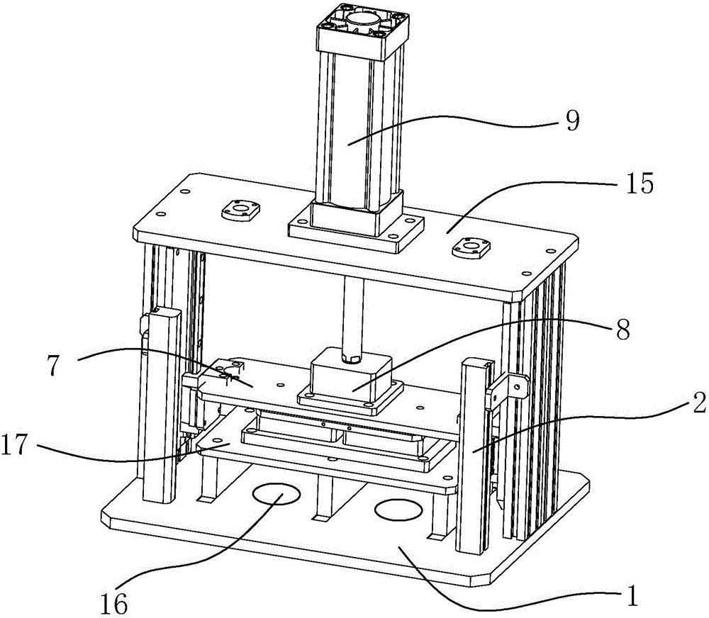
Figure 1 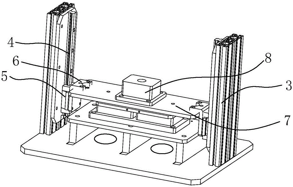
Figure 2 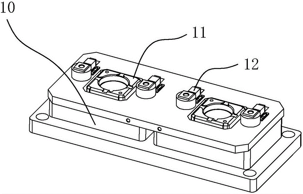
Figure 3
Abstract
Description
technical field
[0001] The invention relates to a cable head manufacturing device adopting electric control grating linkage. Background technique
[0002] The cable joint is also called the cable head. After the cable is laid, in order to make it a continuous line, each section of the line must be connected as a whole, and these connection points are called cable joints. The cable joints in the middle of the cable line are called intermediate joints, and the cable joints at both ends of the line are called terminal heads. The cable joint is used to lock and fix the incoming and outgoing lines, and play the role of waterproof, dustproof and shockproof. Some electrical installation and construction personnel often do not pay attention to the installation quality when laying wires: no sleeve is installed where the insulating sleeve should be used; no junction box is installed where the junction box should be used; even the splicing method is not used at the wire joint , but ...
Examples
Embodiment
[0019] Embodiment: A cable head manufacturing device that adopts electronic control grating linkage, its main structure includes: base plate 1, grating 2, vertical arm rod 3, rail 4, slider 5, connector 6, pressure plate 7, solder cavity 8. Electric air rod 9, mold box 10, cable clamp 11, tin injection contact 12, tin outlet 13, cable harness ring 14, top cover plate 15, cable channel 16, platform plate 17, the The base plate 1 and the top cover plate 15 are fixed and supported by the vertical arm rod 3; the inner side of the vertical arm rod 3 is fixed with a rail 4, and a slider 5 is mounted on the rail 4, and the slider 5 and the pressure plate 7 pass through the connecting piece 6 Phase fixed;
[0020] The central position of the pressing plate 7 is provided with a solder chamber 8; the central position of the top cover plate 15 is provided with an electric air rod 9, and the end of the electric air rod 9 is fixed on the solder chamber 8; 7 is fixed with a tin-injected co...