
Disk inner hole pickup device
A pick-up device and inner hole technology, applied to instruments, record carrier structural parts, data recording, etc., can solve the problems of disc damage, inconvenient pick-up, easy to hold and unstable
Patent Information
- Authority / Receiving Office
- CN · China
- Patent Type
- Applications(China)
- Current Assignee / Owner
- Publication Date
- 2018-01-16
Smart Images
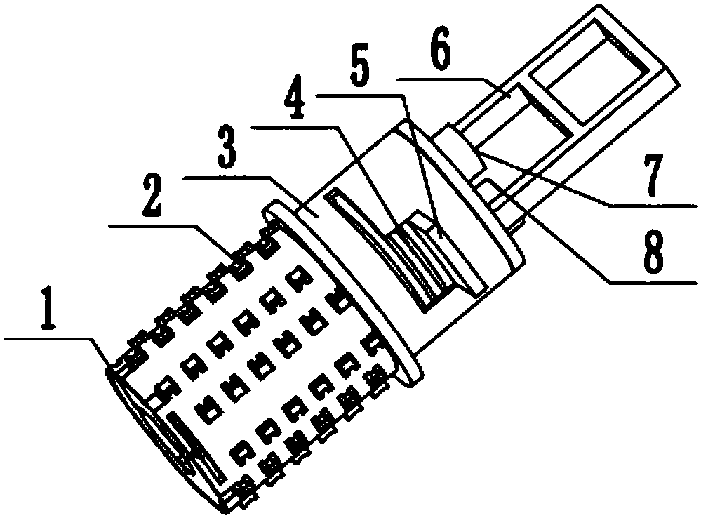
Figure 1 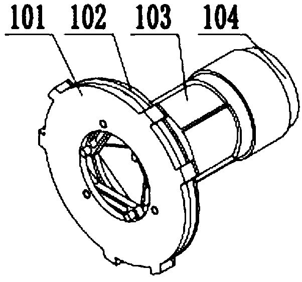
Figure 2 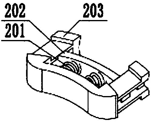
Figure 3
Abstract
Description
technical field
[0001] The invention relates to an optical disc inner hole pick-up device, specifically a disc pick-up device using a protective device, an elastic top block, an outer tube, an air bag expansion device, a handle, a pressure plate, an open button and a close button, and belongs to the field of daily necessities. Background technique
[0002] Optical disc is a kind of item that uses optical information as a storage carrier and is used to store data. Optical disc is a device that uses laser principles to read and write. It is a rapidly developing auxiliary memory that can store various texts, sounds, graphics, For multimedia digital information such as images and animations, as a precision storage device, the storage and pickup of optical discs has become a crucial issue. Due to the particularity of the structure and materials of optical discs, it is very inconvenient to pick up. At this stage, it is mainly divided into There are three pick-up methods. One is to...
Examples
Embodiment Construction
[0024] An optical disc inner hole pick-up device, which is composed of a protective device 1, an elastic top block 2, an outer tube 3, an inner tube 4, a switch 5, a left elastic clip 6 and a right elastic clip 7, and the protective device 1 is fixed on the outer tube 3 Inside the lower end, the elastic top block 2 is divided into three rows, which are uniformly fixed on the cylindrical surface of the lower end of the outer tube 3, the inner tube 4 is placed inside the outer tube 3, and the left elastic clip 6 and the right elastic clip 5 pass through The pins and the second spring are fixed on the upper end of the outer tube 3 and distributed symmetrically, and the switch 5 is installed on the upper surface of the inner tube 4 .
[0025] The protective device 1 includes a lower chassis 101, an upper chassis device 102, a driving device 103 and a battery 104, the lower chassis 101 is connected to the upper chassis device 102, and the driving device 103 is fixed inside the upper...