
High trigger voltage thyristor
A trigger voltage and thyristor technology, applied in the direction of thyristors, diodes, etc., can solve the problems of thyristor false opening, high trigger voltage, low trigger voltage, etc., achieve small packaging stress, improve reliability, and high liquidus Effect
Patent Information
- Authority / Receiving Office
- CN · China
- Patent Type
- Applications(China)
- Current Assignee / Owner
- Publication Date
- 2018-11-23
- Estimated Expiration
- Not applicable · inactive patent
Smart Images
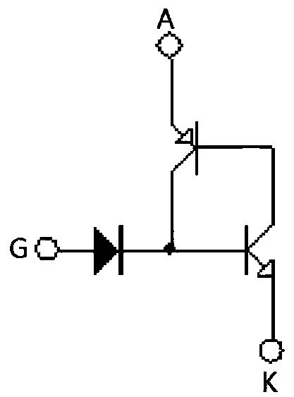
Figure 1 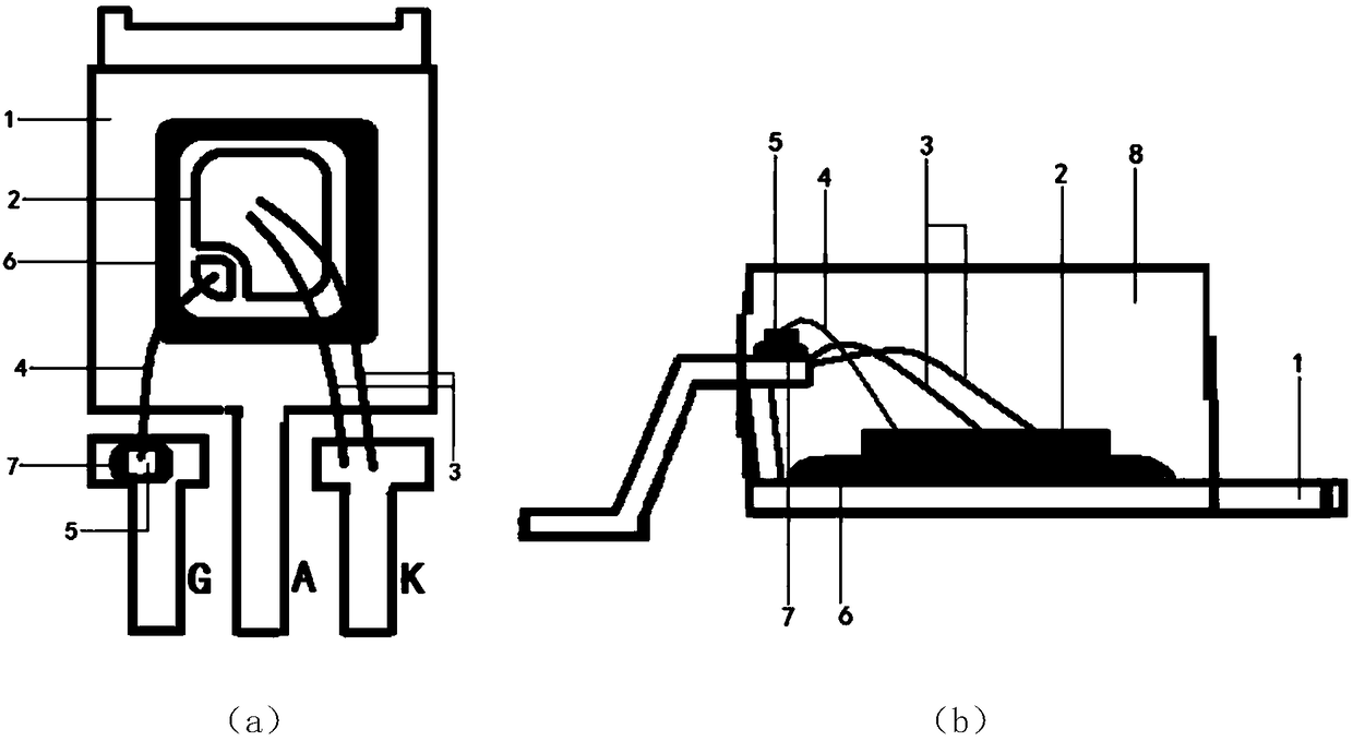
Figure 2 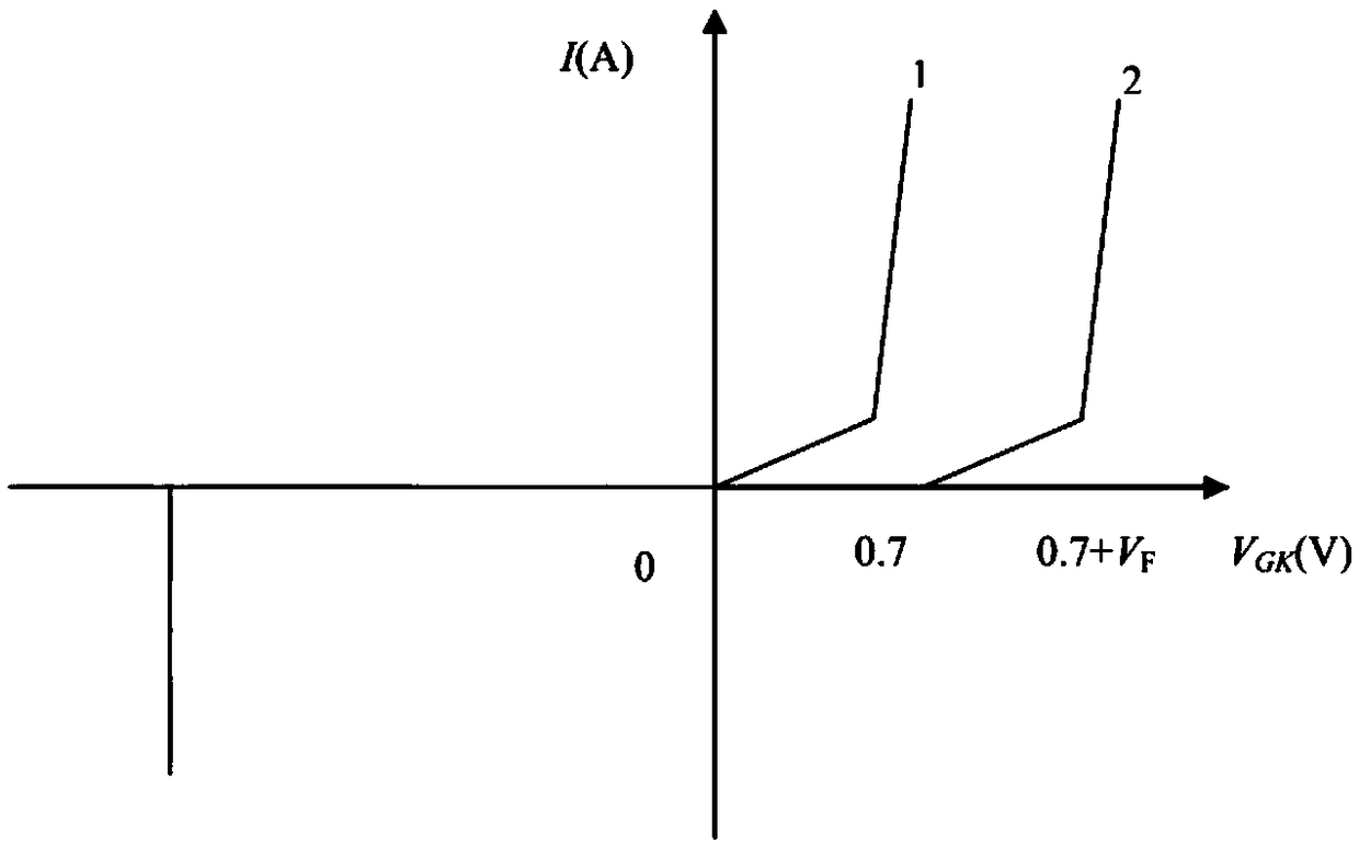
Figure 3
Abstract
Description
Technical field
[0001] The invention belongs to the technical field of semiconductor components, in particular to a high trigger voltage thyristor.
Background technique
[0002] The thyristor is a high-power semiconductor device with a four-layer structure of three PN junctions, also known as a thyristor. With the characteristics of small size, relatively simple structure, and strong functions, it is one of the more commonly used semiconductor devices. The device is widely used in various electronic equipment and electronic products, and is mostly used for controllable rectification, inverter, frequency conversion, voltage regulation, non-contact switch, etc. Dimming lamps, speed-adjusting fans, air conditioners, televisions, refrigerators, washing machines, cameras, combined audio systems, sound and light circuits, timing controllers, toy devices, radio remote controls, cameras and industrial controls in household appliances are widely used A thyristor device. [000...
Examples
Embodiment 1
[0033] S1: First select a metal frame, which is a KFC (CuFe_0.1P_0.03) copper frame with a thickness of 0.5 mm.
[0034] S2: Point solder on the PAD of the anode A on the copper frame, the solder is Pb / Sn / Ag=92.5:5:2.5, and point conductive silver paste on the PAD of the control pole G of the copper frame.
[0035] S3: Glue a thyristor chip on the solder on the PAD of the anode A on the copper frame, and glue a diode chip on the conductive silver paste on the PAD of the control electrode G of the copper frame. By sintering, the thyristor chip is well adhered to the anode A on the copper frame, and the diode chip is well adhered to the gate G of the copper frame.
[0036] S4: Pressure-weld two high-purity aluminum wires between the larger cathode bonding area of the thyristor chip and the K-electrode pin of the copper frame. The high-purity aluminum wires have a purity of 99.99% and a diameter of 12 mils.
[0037] S5: Press-weld a high-purity gold wire between the small cont...
Embodiment 2
[0040] S1: First select a metal frame, which is a KFC (CuFe_0.1P_0.03) copper frame with a thickness of 0.5 mm.
[0041] S2: Point solder on the PAD of the anode A on the copper frame, the solder is Pb / Sn / Ag=92.5:5:2.5, and point conductive silver paste on the PAD of the control pole G of the copper frame.
[0042]S3: Glue a thyristor chip on the solder on the PAD of the anode A on the copper frame, and glue a diode chip on the conductive silver paste on the PAD of the control electrode G of the copper frame. By sintering, the thyristor chip is well adhered to the anode A on the copper frame, and the diode chip is well adhered to the gate G of the copper frame.
[0043] S4: Pressure-weld two high-purity aluminum wires between the relatively large cathode bonding area of the thyristor chip and the K-electrode pin of the copper frame. The high-purity aluminum wires have a purity of 99.99% and a diameter of 10 mils.
[0044] S5: Press-weld a high-purity gold wire between the s...
Embodiment 3
[0047] S1: First select a metal frame, which is a KFC (CuFe_0.1P_0.03) copper frame with a thickness of 0.5 mm.
[0048] S2: Point solder on the PAD of the anode A on the copper frame, the solder is Pb / Sn / Ag=92.5:5:2.5, and point conductive silver paste on the PAD of the control pole G of the copper frame.
[0049] S3: Glue a thyristor chip on the solder on the PAD of the anode A on the copper frame, and glue a diode chip on the conductive silver paste on the PAD of the control electrode G of the copper frame. By sintering, the thyristor chip is well adhered to the anode A on the copper frame, and the diode chip is well adhered to the gate G of the copper frame.
[0050] S4: Pressure-weld two high-purity aluminum wires between the relatively large cathode bonding area of the thyristor chip and the K-electrode pin of the copper frame. The high-purity aluminum wires have a purity of 99.99% and a diameter of 15 mils.
[0051] S5: Press-weld a high-purity gold wire between the ...