
a space reserve
A space and complete technology, applied in the field of space-based weapons, can solve the problems of large overall size envelope, low distribution density of internal storage parts, and lack of adaptability
Patent Information
- Authority / Receiving Office
- CN · China
- Patent Type
- Patents(China)
- Current Assignee / Owner
- Publication Date
- 2021-04-20
Smart Images
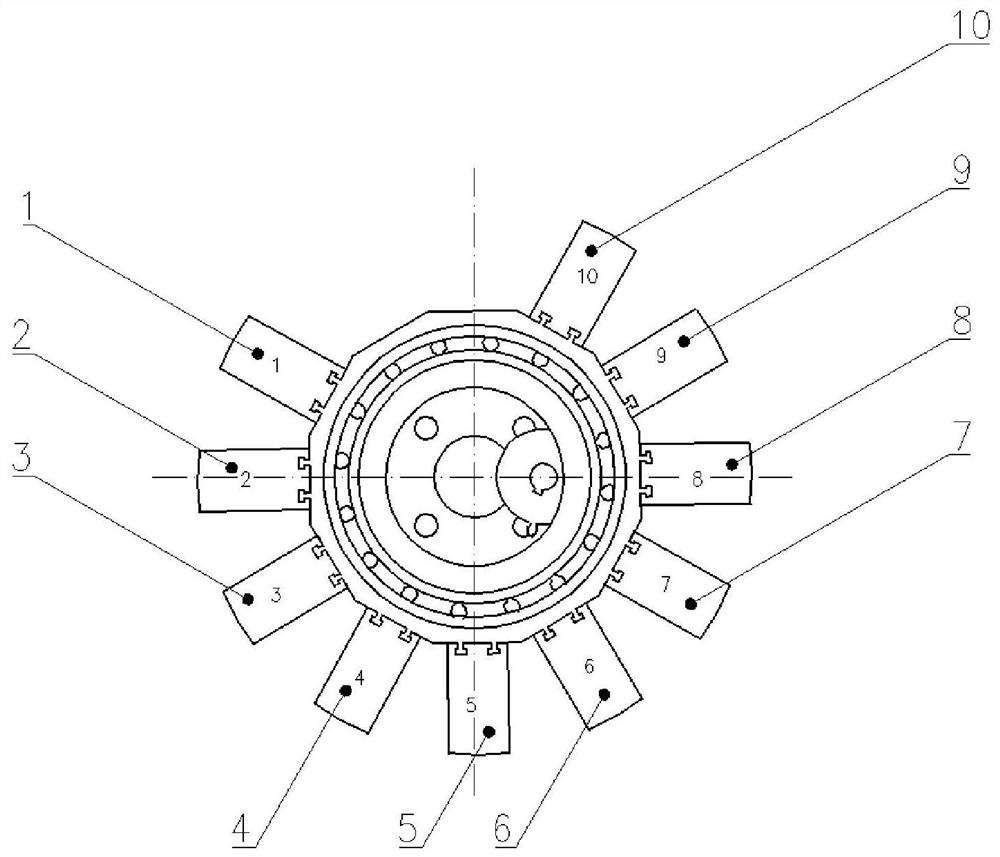
Figure 1 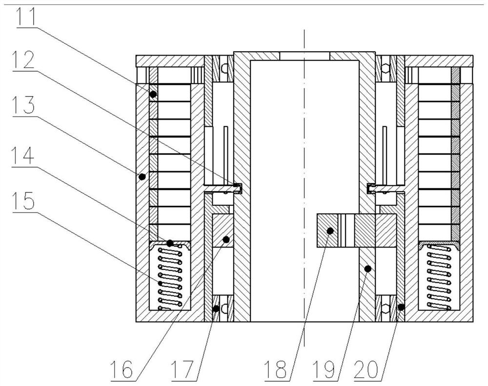
Figure 2 
Figure 3
Abstract
Description
technical field
[0001] The invention relates to the technical field of space-based weapons, in particular to a space reserve mechanism. Background technique
[0002] In order to ensure that a launch system continuously launches the armature, it is necessary to store a certain number of armatures for the launch system, and transport the armatures to the muzzle position in order to prepare for pushing the armature. The storage mechanism needs to solve the problems of large armature capacity, reliable delivery in place, and adaptation to the shape of the armature.
[0003] Among the existing storage mechanisms, the storage mechanisms in the form of drums, magazines, and spiral magazines used in automatic firearms have a large capacity for storage parts, but they are limited to regular storage parts and do not have the ability to adapt to non-standard storage parts. due to the weightlessness effect of the space environment, the adaptability of the bullet chain to the space envi...
Examples
Embodiment Construction
[0025] The present invention will be described in detail below with reference to the accompanying drawings and examples.
[0026] The space reserve mechanism provided by the present invention, such as figure 1 , figure 2 As shown, it includes ten clip assemblies, an incomplete internal gear 16, a bearing 17, an incomplete external gear 18, a fixed roller 19, and a movable roller 20; the storage part is an armature 11.
[0027] The movable drum 20 is coaxially arranged outside the fixed drum 19, and forms a rotating pair with the fixed drum 19 through the bearing 17. The ten clip components are: clip I1, clip II2, clip III3, clip IV4, clip V5, clip VI6, clip VII7, clip VIII8, clip IX9, clip X10, ten pieces The clip assembly is installed on the outer circumference of the movable drum 20 successively. The clip assembly is provided with a shift fork, and the roller 12 is installed at the end of the shift fork, which fits with the cylindrical cam groove provided on the outer cir...