
Automatic photovoltaic panel frame 45-degree sawing machine
A photovoltaic panel, automatic technology, applied in metal sawing equipment, sawing machine equipment, metal processing equipment, etc., can solve the problems of inability to guarantee the stability and accuracy of sawing, and the inability to fix the photovoltaic panel frame, so as to ensure safety. With the effect of stability, good self-locking, simple and convenient operation
Patent Information
- Authority / Receiving Office
- CN · China
- Patent Type
- Applications(China)
- Current Assignee / Owner
- Publication Date
- 2019-05-17
- Estimated Expiration
- Not applicable · inactive patent
Smart Images
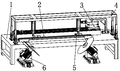
Figure 1 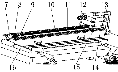
Figure 2 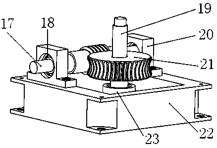
Figure 3
Abstract
Description
technical field
[0001] The invention relates to an automatic 45° sawing machine for a frame of a photovoltaic panel. Background technique
[0002] When sawing the frame of the photovoltaic panel, the frame of the photovoltaic panel should be aligned, adjusted and pressed tightly to ensure the stability during sawing. There are many traditional sawing mechanisms on the market. Traditional sawing mechanisms are used to compress parts with regular cross-sections. Most of them are semi-automatic. They cannot accurately fix the L-shaped photovoltaic panel frame and cannot guarantee the accuracy of sawing. stability and precision. Contents of the invention
[0003] The invention discloses an automatic 45° sawing machine for a frame of a photovoltaic panel.
[0004] The basic technical solution is: an automatic photovoltaic panel frame 45° sawing machine consists of a workbench, a motion platform, a linear guide rail, a slider, a ball screw, a slide table, a screw nut, a screw ...
Examples
Embodiment Construction
[0017] Below in conjunction with the accompanying drawings, the components and their interrelationships of the present invention will be described.
[0018] Overall structure of the present invention is as attached figure 1 As shown, the moving platform (2) is fixed on the workbench (1), the rotating mechanism (3) is connected with the sliding platform one (14) on the movement platform (2), and the fixed frame (4) is connected with the workbench (1) , the pushing alignment mechanism (5) is installed in the workbench (1), and the sawing mechanism (6) is fixed at the bottom of the workbench (1). as attached figure 2 , 3 , 4, 5, and 6, the connecting bearings at both ends of the long ball screw (10) are fixed on the screw fixing seat (9) and the screw support seat, and the slide table (14) is fixed on the four sliders (15 ), the motor (8) is fixed on the motion platform (2) through the motor bracket (7), and connected with the long ball screw (10) through the coupling, and th...