
Intelligent fragile product clamping tool
A technology for clamping tooling and fragile products, applied in the field of tooling fixtures, can solve the problems of large damage to human glasses, slow jaw opening and closing speed, and low production efficiency
Patent Information
- Authority / Receiving Office
- CN · China
- Patent Type
- Applications(China)
- Current Assignee / Owner
- Publication Date
- 2019-07-05
Smart Images
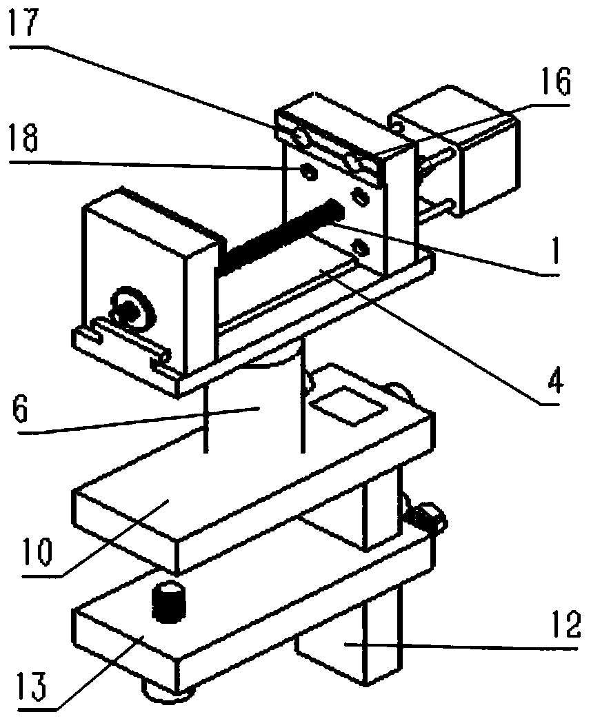
Figure 1 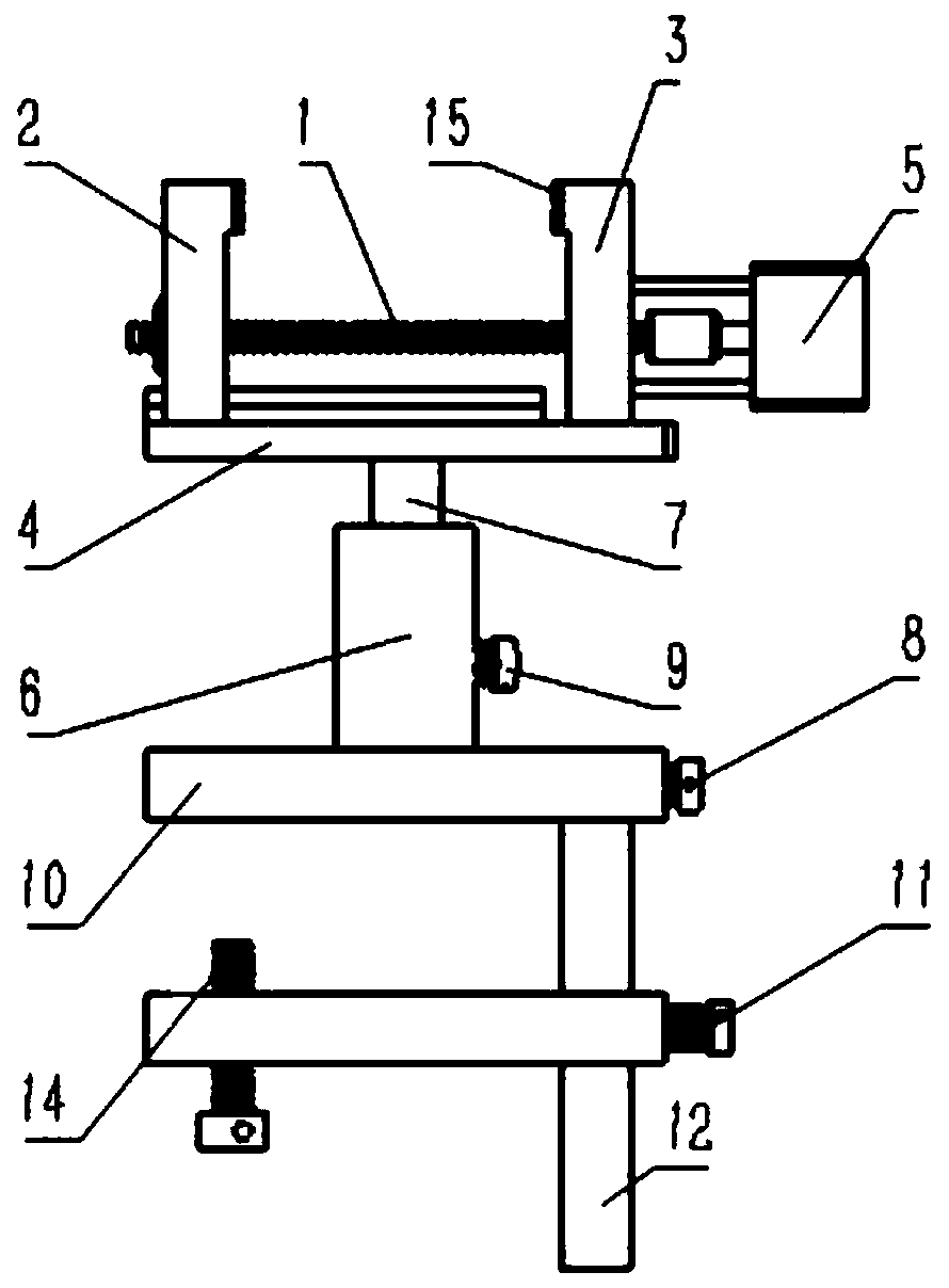
Figure 2 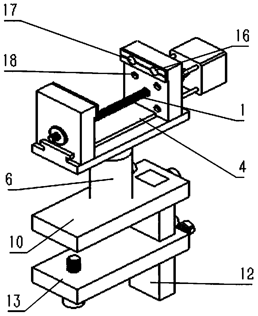
Figure 3
Abstract
Description
technical field
[0001] The invention relates to a novel intelligent clamping tool for fragile products, which belongs to the field of tool fixtures. Background technique
[0002] At present, most of the clamping devices for fragile or deformable products rely on the production experience of the workers to give the pre-tightening force. During the clamping process, the pre-tightening force will affect the product quality, and the pre-tightening force will affect the product quality. If the pre-tightening force is too small, it may cause the product to swing. At present, most clamping device designs are not flexible enough. The present invention installs a pressure sensor and an ultrasonic sensor on the fixed jaw, can intelligently and automatically move the movable jaw and control the pre-tightening force, and at the same time has a simple structure, adopts a mechanical structure, can complete 360-degree rotation in the horizontal plane, and passes through the fixed bracket ...
Examples
Embodiment Construction
[0019] The present invention will be further described in conjunction with the above accompanying drawings.
[0020] An intelligent clamping tool for fragile products, the clamping tool includes fixed jaws (3), movable jaws (2), rubber pads (15), pressure sensors (16), ultrasonic sensors (17), vise guide rails (4), stepping motor (5), screw slide (1), rotating shaft (7), rotating shaft outer casing (6), fixing bracket (12), adjustable fixing screw (8), adjustable screw ( 14), limiting plate (10) and movable limiting device (13).
[0021] The positions of the fixed jaws (3) and the movable jaws (2) are corresponding, and the fixed jaws (3) and the vise guide rail (4) are tightly connected; the bottom of the vise guide rail (4) is connected to the rotating shaft ( 7) Connection; the movable jaw (2) is installed on one side of the guide rail (4) of the guide rail vise, the movable jaw (2) and the guide rail of the guide rail vise (4) are slidingly fitted, and the fixed jaw (3) a...