
A microwave load for 0-6ghz calorimetric microwave power meter
A microwave power meter and microwave technology, applied in the direction of measuring electric power, electrical devices, measuring devices, etc., can solve the problems of insufficient precision of the coupling measurement method and the inability to measure the microwave and millimeter wave power of several watts to hundreds of watts, so as to improve the Measurement accuracy, easy and precise control and measurement, and the effect of widening the power measurement range
Patent Information
- Authority / Receiving Office
- CN · China
- Patent Type
- Patents(China)
- Current Assignee / Owner
- Publication Date
- 2020-12-01
Smart Images
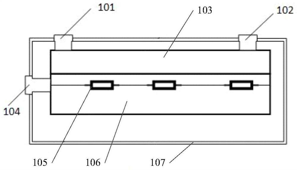
Figure 1 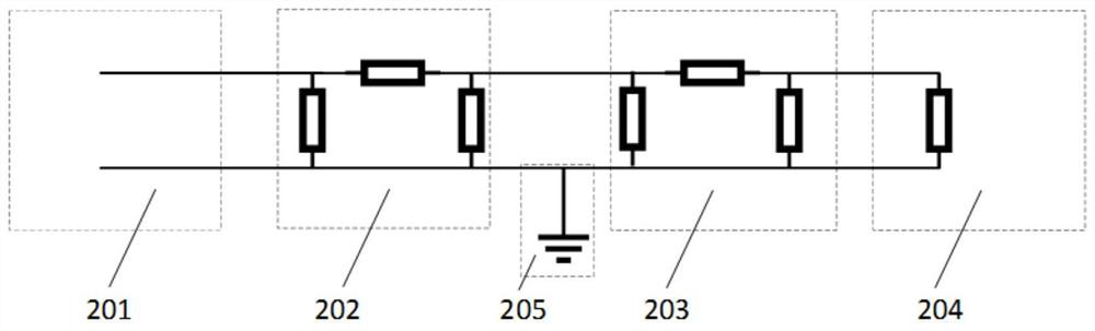
Figure 2 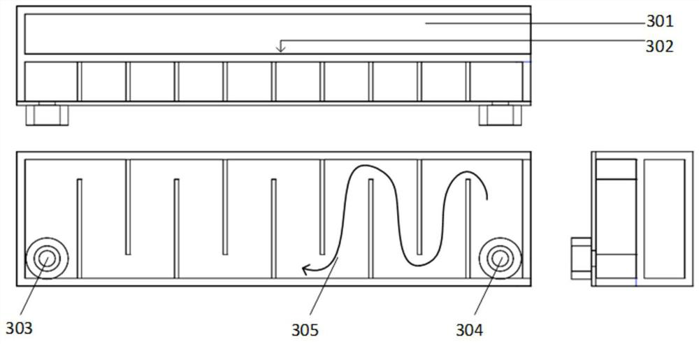
Figure 3
Abstract
Description
technical field
[0001] The invention relates to the field of microwave power measurement, in particular to a microwave load for a 0-6GHz calorimetric microwave power meter. Background technique
[0002] Accurate measurement of medium and low microwave power is very important for industrial production and national defense technology. Generally, low-power microwave (milliwatt level) can be directly and accurately measured by existing commercial equipment. When measuring medium and low power (several watts to hundreds of watts) microwaves, an equal proportion of low power microwaves can be obtained through a directional coupler, and then the low power microwaves can be directly measured, and then the microwave power can be obtained according to the coupling coefficient of the device used, but this device The coupling coefficient will change at different frequencies and different powers, resulting in low measurement accuracy. Calorimetric water load can also be used for microwa...
Examples
Embodiment Construction
[0029] In order to understand the above-mentioned purpose, features and advantages of the present invention more clearly, the present invention will be further described in detail below in conjunction with the accompanying drawings and specific embodiments. It should be noted that, under the condition of not conflicting with each other, the embodiments of the present application and the features in the embodiments can be combined with each other.
[0030] In the following description, many specific details are set forth in order to fully understand the present invention. However, the present invention can also be implemented in other ways different from the scope of this description. Therefore, the protection scope of the present invention is not limited by the following disclosure. limitations of specific examples.
[0031] The system structure of the present invention is as figure 1 As shown, it includes a liquid channel inlet 101 , a liquid channel outlet 102 , a liquid ci...