
Railway vehicle wheel with improved damping characteristics
A railway vehicle and wheel technology, which is applied in the direction of wheels, wheels, and vehicle parts characterized by track running parts, and can solve problems such as large radial elasticity
Patent Information
- Authority / Receiving Office
- CN · China
- Patent Type
- Patents(China)
- Current Assignee / Owner
- Publication Date
- 2003-04-23
- Estimated Expiration
- Not applicable · inactive patent
Smart Images
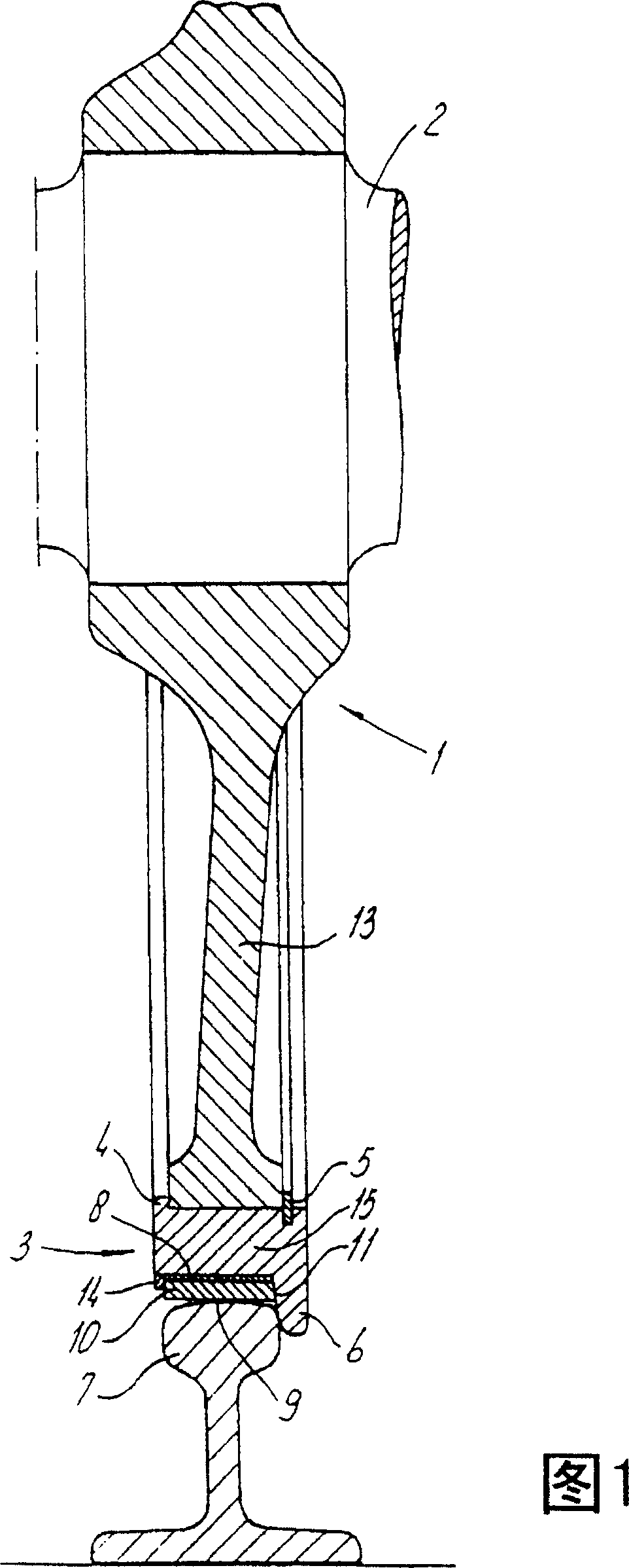
Figure 1 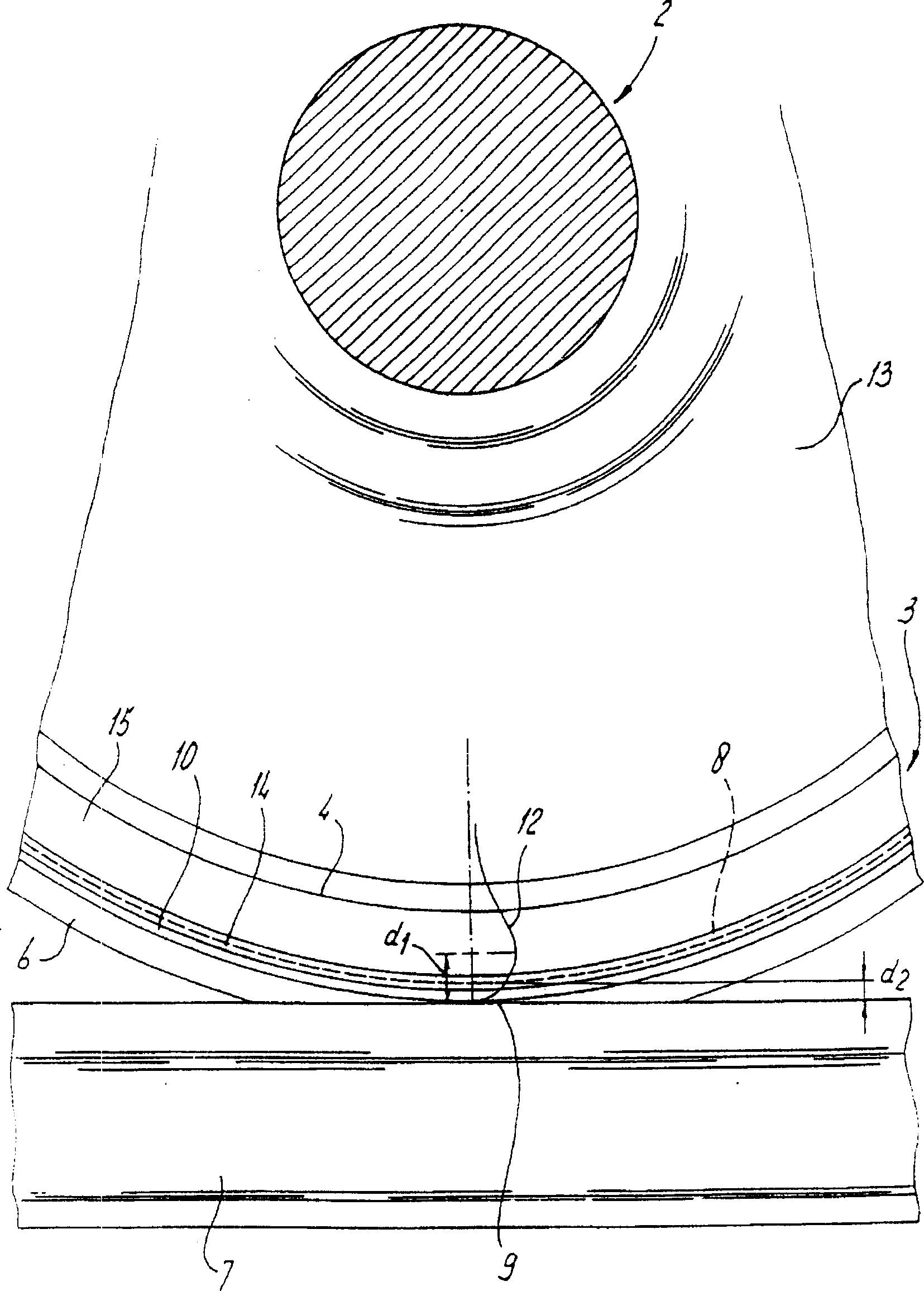
Figure 2 
Figure 3
Abstract
Description
technical field
[0001] The invention relates to a railway vehicle wheel comprising a hub and a rim with a rim, the hub and the rim are connected together by a disc or spokes. Background technique
[0002] In operation, the contact between rail and rail forms a vibration source, which transmits vibrations to the wheel axle. Naturally, these vibrations are applied to the bearings and ultimately to the superstructure of the locomotive and vehicle. In this way, the passengers will feel uncomfortable, and in addition, the fatigue degree of the steel material of the axle and the wheel will be increased.
[0003] From US-A-5183306, a known railway vehicle wheel comprises a rubber ring arranged between the hub and the rim of the wheel. In radial section, the aforementioned rubber ring has a U-shaped shape, resulting in radial shearing of the rubber material. The rubber ring has the same thickness as the rim.
[0004] Disadvantages of this known railway vehicle wheel are its cons...
Examples
Embodiment Construction
[0022] As shown in FIG. 1 , a railway vehicle wheel 1 comprises a hub 2 and a rim 3 , which are connected to each other via connecting discs 13 . The rim 3 has an inwardly protruding edge 4 which together with the clamping ring 5 provides the required connection between said rim 3 and the connection disc 13 .
[0023] The rim 3 has a flange 6 for guiding the wheel of the railway vehicle relative to the rail 7 .
[0024] According to the invention, the rim 3 has a thin layer 8 of viscoelastic material at a certain distance from its running surface 9 .
[0025] As in the embodiment shown, the viscoelastic layer 8 is covered with a steel ring 10 resting on one side against the facing surface 11 of the rim 6 .
[0026] The steel ring 10 of the rim 3 and the main ring body 15 are firmly fixed together by a fixing ring. The fixing ring 14 is fixed on the main ring body 15 through an interference fit, so the viscoelastic layer 8 and the steel ring 10 are fixed between the fixing ri...