
Agricultural three-jaw rake bending equipment
An agricultural and bending technology, which is applied in the field of agricultural three-claw iron rake bending equipment, can solve the problems of low work efficiency, cumbersome operation process, and labor-intensive
Patent Information
- Authority / Receiving Office
- CN · China
- Current Assignee / Owner
- Publication Date
- 2021-05-11
Smart Images
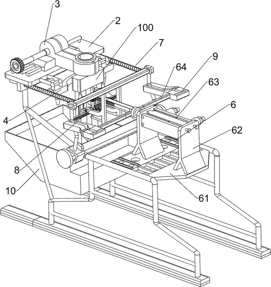
Figure 1 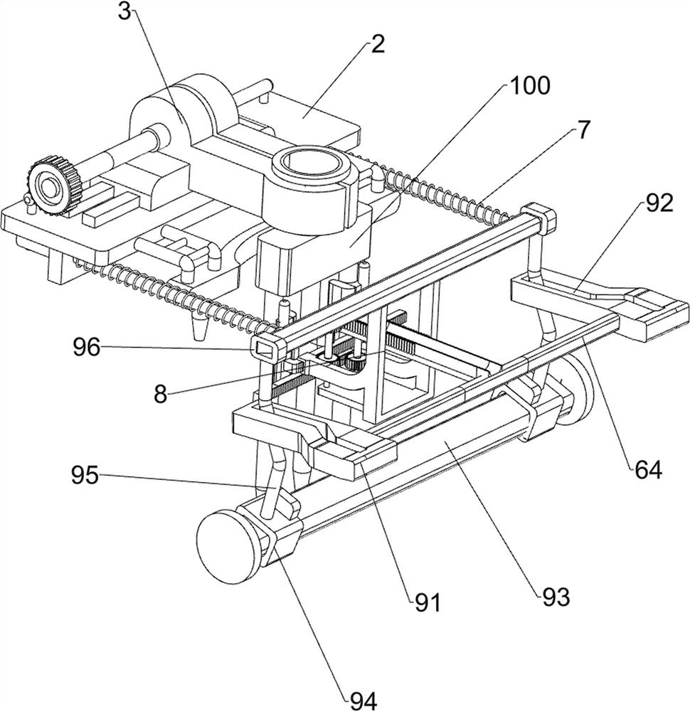
Figure 2 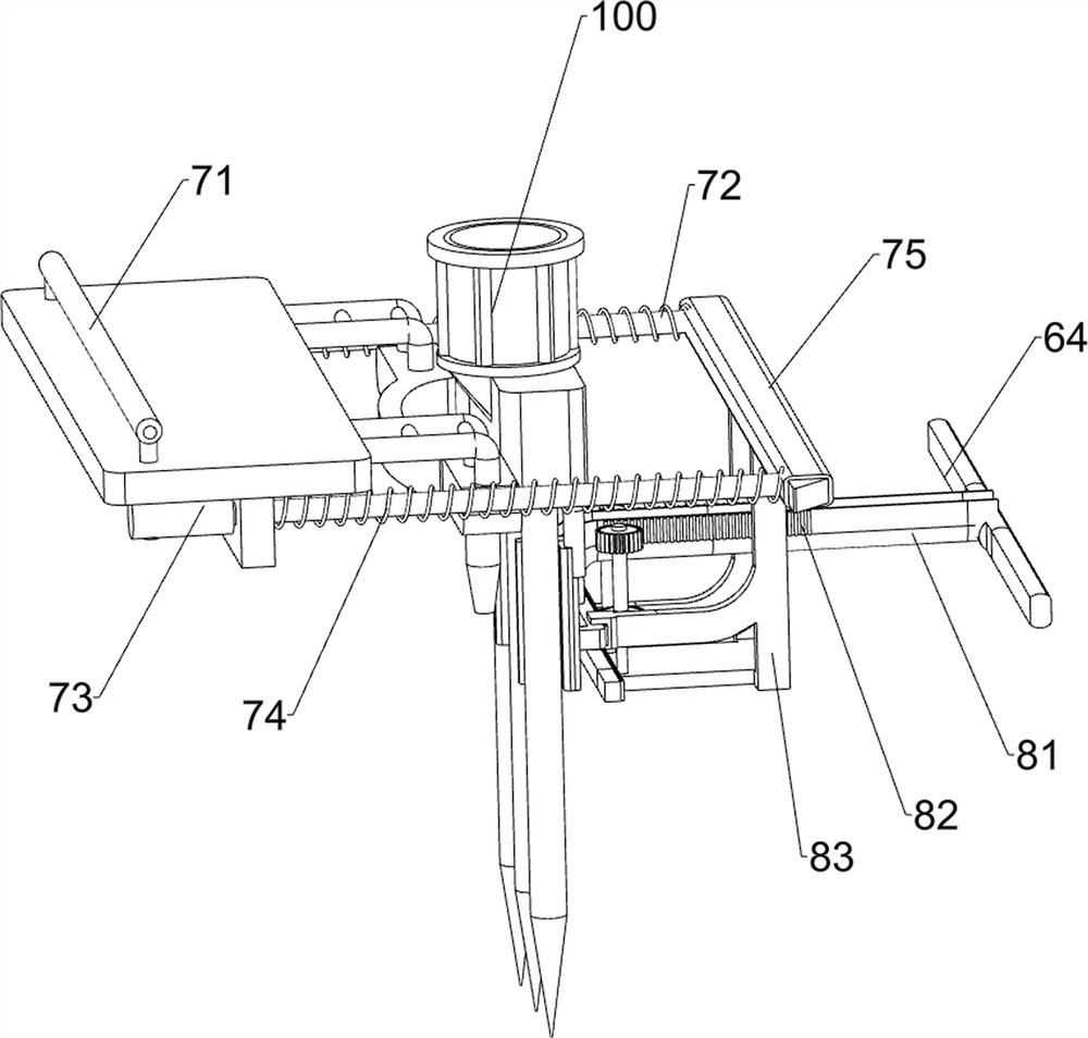
Figure 3
Abstract
Description
technical field
[0001] The invention relates to a bending device, in particular to an agricultural three-claw iron rake bending device. Background technique
[0002] With the continuous development of modern society and the improvement of people's quality of life, agriculture is an important part of modern society. Agriculture is an industry that utilizes the growth and development laws of plants to produce products through artificial cultivation. Agriculture belongs to the primary industry. In the process of agricultural planting, iron rakes are usually used, and iron rakes are mostly set with three claws. During the production process of iron rakes, it is usually necessary to bend the three rake bars on the iron rake embryo body before installing them.
[0003] At present, the way to bend the iron rake is usually to place the iron rake on the limit device. After placing the iron rake, the user operates the sleeve rod to block the rake rod of the iron rake. Driving the iro...
Examples
Embodiment 1
[0026] An agricultural three-claw iron rake bending equipment, such as Figure 1-5 As shown, it includes a frame 1, a fixed plate 2, a clamp table 3, a mounting frame 4 and a positioning rod 5. The left side of the top of the frame 1 is connected with a fixed plate 2, and the fixed plate 2 is equipped with a clamp table 3 and a fixed plate 2. The right side is connected with a mounting frame 4, and both sides of the bottom of the mounting frame 4 are connected with positioning rods 5, and also include an extrusion mechanism 6, a positioning guide assembly 7 and a bending mechanism 8, and the frame 1 is provided with an extrusion mechanism 6, The fixed plate 2 is provided with a positioning guide assembly 7, and a bending mechanism 8 is provided between the positioning guide assembly 7 and the extruding mechanism 6, and the extruding mechanism 6 and the bending mechanism 8 are connected by transmission.
[0027] The extruding mechanism 6 includes a mounting plate 61, a mounting...
Embodiment 2
[0032] On the basis of Example 1, such as figure 2 with Figure 5 As shown, an automatic guide mechanism 9 is also included, and the automatic guide mechanism 9 includes a guide plate 91, a guide rail 93, a sliding sleeve 94, a connecting rod 95, a ferrule 96 and a wedge block 97, and both sides of the extruding rod 64 are connected with guides. Plate 91, has guide groove 92 on guide plate 91, and frame 1 middle part is connected with guide rail 93, and guide rail 93 front and rear both sides are all slidably connected with sliding sleeve 94, is connected with connecting rod 95 on the sliding sleeve 94, two connecting rods 95 are slidingly matched with the guide slots 92 on the two guide plates 91 respectively. The top of the connecting rod 95 is connected with a ferrule 96.
[0033]Initially, the n-type clamping rod 71 can be directly extracted, and the extruding rod 64 drives the guide plate 91 to move to the left when moving to the left. Since the wedge-shaped block 97 is...