

Box-type switching station
A switch station and box-type technology, applied in substation/switch layout details, substation/switchgear cooling/ventilation, electrical components, etc., can solve the problems of limited operating space for staff, difficult deployment, and reduced service life of components. , to achieve the effect of increasing display space, increasing heat dissipation efficiency, and improving work efficiency
Patent Information
- Authority / Receiving Office
- CN · China
- Patent Type
- Applications(China)
- Current Assignee / Owner
- Publication Date
- 2021-07-16
- Estimated Expiration
- Not applicable · inactive patent
Smart Images
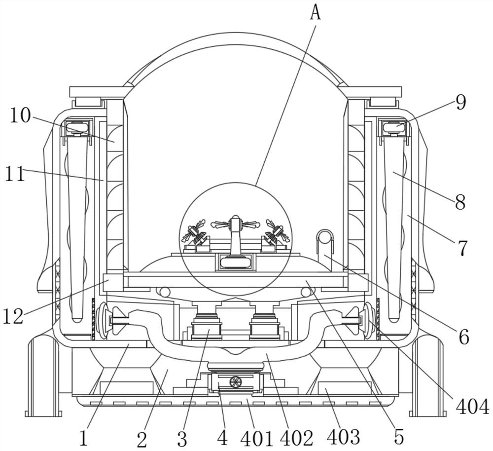
Figure 1 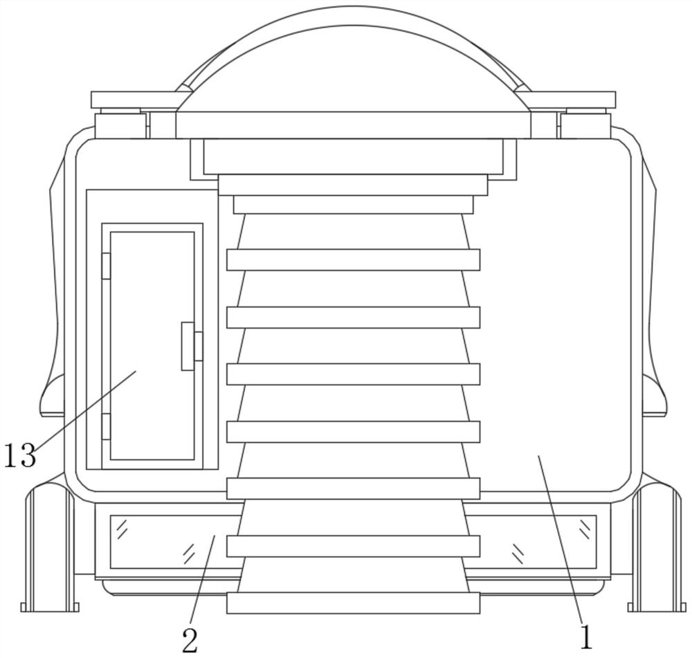
Figure 2 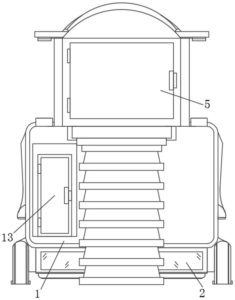
Figure 3
Abstract
Description
technical field
[0001] The invention relates to the technical field of power distribution equipment, in particular to a box-type switchgear. Background technique
[0002] The switch station refers to the power supply and distribution facilities used to receive and distribute power. The high-voltage power grid is called a switch station. The switch station in the medium-voltage power grid is generally used for receiving and distributing 10kV power. There is a medium-voltage power distribution facility. The power distribution device for incoming and outgoing lines and redistribution of power is equivalent to the extension of the substation busbar. It can be used to solve the limited interval between the incoming and outgoing lines of the substation or the restricted corridor of the incoming and outgoing lines, and play the role of power supply in the area.
[0003] The current box-type switchgear is generally installed and installed outside. However, the outside climate is cha...
Examples
Embodiment 1
[0038] Example 1, such as figure 1 As shown, the humidity under the equipment is detected by the humidity sensor 403. When the humidity reaches a certain index, the suction fan 4 and the servo motor 9 can be started through the control box 13, and the cooling gas inside the inner box 5 is released from the exhaust port 10. After the outflow, the start of the servo motor 9 can drive the spiral guide rod 8 to guide the gas downward, and after the gas is introduced into the lower part, the start of the suction fan 4 and the communication and cooperation of the shunt pipe 402 and the suction port 404 will guide the flow. The gas under the wind chamber 7 is absorbed, and the absorbed gas flows into the permeable plate 401 under negative pressure, and through the evenly distributed through holes of the permeable plate 401, the absorbed heat dissipation gas evenly covers the bottom groove 2 and the bottom of the permeable plate 401, Furthermore, the moisture sensed by the humidity se...
Embodiment 2
[0039] Example 2, such as Figure 1-3 As shown, the temperature in the inner box 5 is detected by the temperature sensor 6. When the temperature in the inner box 5 is high, the electric push rod 3 can be started through the control box 13, and the start of the electric push rod 3 is used to drive the inner box. The box body 5 is lifted as a whole, and during the rising of the inner box body 5, four groups of guide blocks 12 are driven to slide and rise under the cooperation of the guide rail columns 11, so that the inner box body 5 can be fully expanded out of the outer box body 1. At this time, the first The fan blades 145 and two sets of second fan blades 146 perform heat dissipation, and the radiated gas can be directly discharged from the exhaust port 10 to speed up the circulation of the gas, prevent the heat source from being concentrated in the equipment and affect the components, and use steps and platforms to After the inner box body 5 is unfolded, the structural comp...