
Micro coaxial radio frequency probe card
A technology of probe card and radio frequency, which is applied in the field of probe card and can solve the problem of unsatisfactory shielding effect
Patent Information
- Authority / Receiving Office
- CN · China
- Patent Type
- Applications(China)
- Current Assignee / Owner
- Publication Date
- 2021-09-10
Smart Images
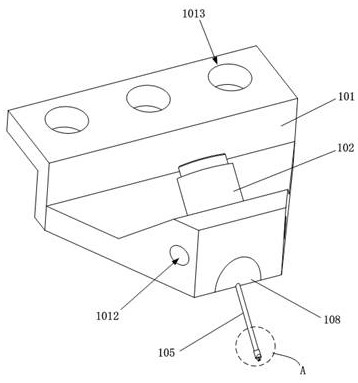
Figure 1 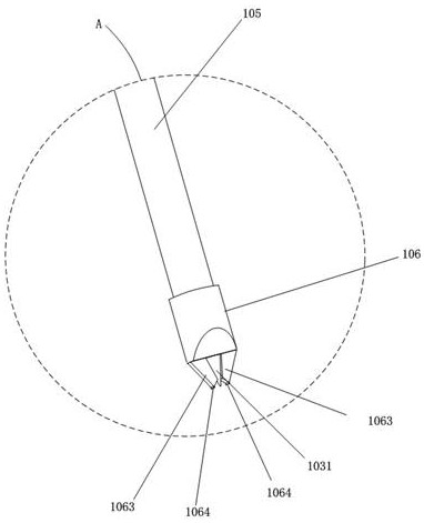
Figure 2 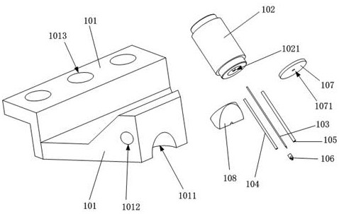
Figure 3
Abstract
Description
technical field
[0001] The invention relates to the technical field of probe cards, in particular to a micro-coaxial radio frequency probe card. Background technique
[0002] The transmission lines used in RF applications are generally coaxial cables connected to the circuit board, and microstrip lines arranged inside the circuit board. An RF probe is a measurement device used in electronic test equipment to measure radio frequency (RF) signals from electronic circuits in silicon wafers, dies, and open microchips. Additionally, RF probes are used in narrow pitch or high density RF interconnect applications in connector assemblies. Before the development of RF probes in 1980, there was no easy way to test monolithic microwave integrated circuit (MMIC) devices without mounting or bonding, so the test process often caused circuit integrity to be compromised. damage, causing system disturbances or reducing electrical loads. The first generation of RF probes used coplanar cera...
Examples
Embodiment Construction
[0026] The following will clearly and completely describe the technical solutions in the embodiments of the present invention with reference to the accompanying drawings in the embodiments of the present invention. Obviously, the described embodiments are only part of the embodiments of the present invention, not all of them. Based on the embodiments of the present invention, all other embodiments obtained by persons of ordinary skill in the art without creative efforts fall within the protection scope of the present invention.
[0027] It should be noted that all directional indications (such as up, down, left, right, front, back...) in the embodiments of the present invention are only used to explain the relationship between the components in a certain posture (as shown in the figure). Relative positional relationship, movement conditions, etc., if the specific posture changes, the directional indication will also change accordingly.
[0028] In addition, the technical solut...