
Coated yarn spinning method and apparatus
A technology of core-spun yarn and core yarn, which is applied in the field of spinning core-spun yarn, which can solve the problems of high production cost, long process flow, and large production investment of core-spun yarn, and achieve reduced production cost, simple equipment structure, and high process flow. short effect
Patent Information
- Authority / Receiving Office
- CN · China
- Current Assignee / Owner
- Publication Date
- 2004-01-21
- Estimated Expiration
- Not applicable · inactive patent
Smart Images
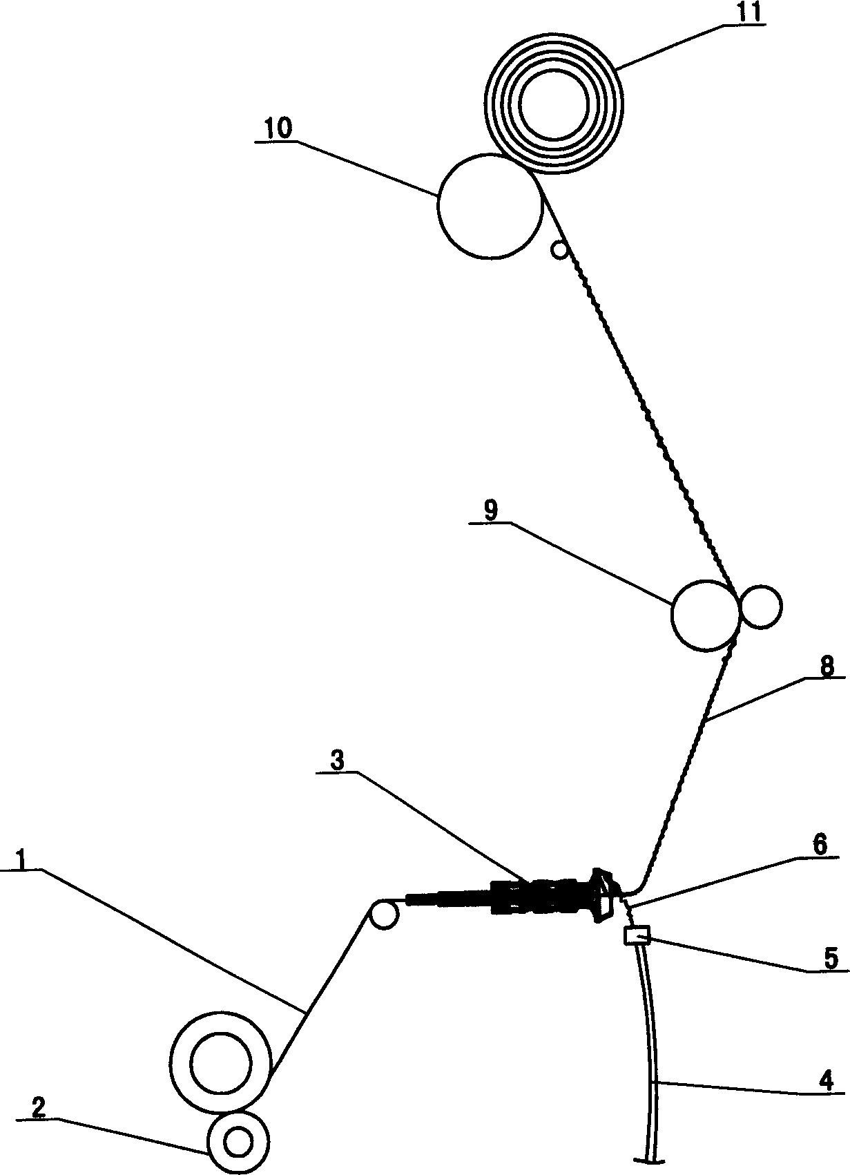
Figure 1 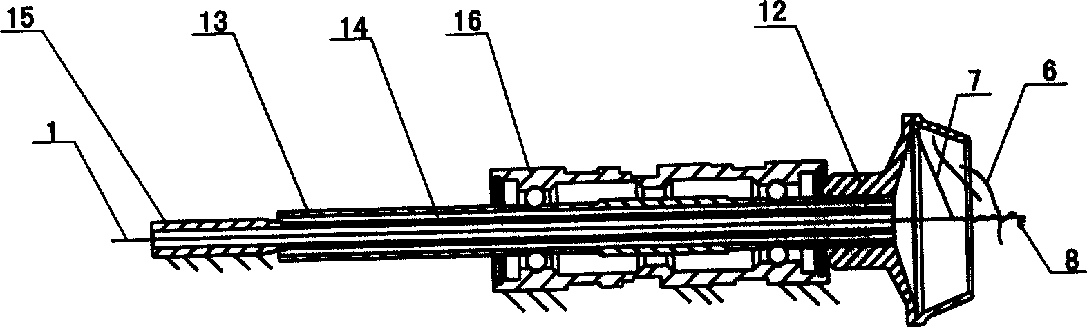
Figure 2 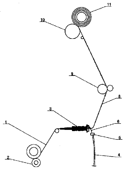
Figure 3
Abstract
Description
Technical Field
[0001] The invention relates to a method and equipment for spinning core-spun yarn.
Background technique
[0002] At present, the production process of core-spun yarn can be roughly divided into the following three types: The first process is sliver-roving frame-spinning frame (with core yarn added)-forming core-spun yarn, and the sliver is stretched on the roving frame. It is twisted and wound by the roving spindle to form a roving bobbin; the roving on the roving bobbin is fed to the drafting roller of the spinning frame, and the roving is drafted into a spun yarn. At the same time, the core yarn is also fed to the spinning frame through the feeding roller. The two draft rollers are twisted together to form a core-spun yarn. The second process flow is sliver-roving frame-spinning frame-covering yarn frame (with core yarn added)-forming core-spun yarn. The sliver is continuously drafted and thinned by the thick and spinning frame, and then twisted to form cot...
Examples
Embodiment Construction
[0011] As shown in the figure, the equipment for spinning core-spun yarn is the rotor spinning machine, including the core yarn feeding roller 2, the yarn take-up roller 9, the winding system 10, the rotor 3 and the opening mechanism 5, and the rotor 3 It includes a rotor cup 12, a rotor cup shaft 13 connected with the rotor cup 12, and a bearing 16. An axial through hole 14 is provided at the axis of the rotor cup shaft 13, and a hollow thread-drawing tube 15 is sheathed in the axial through hole 14, and One end of the yarn-drawing tube 15 is flush with the rotor shaft 13, and the other end extends out of the axial through hole 14. The yarn-drawing tube 15 and the bearing 16 are fixed on the frame of the rotor spinning machine. The fit of the axial through hole 14 in the cup shaft is a clearance fit. The winding system 10 is a winding roller, and other components such as the core yarn feeding roller 2 and the yarn take-up roller 9 are well-known common components, and the connect...