
Electromagnetic valve
Patent Information
- Authority / Receiving Office
- US · United States
- Current Assignee / Owner
- Publication Date
- 2005-08-04
Smart Images
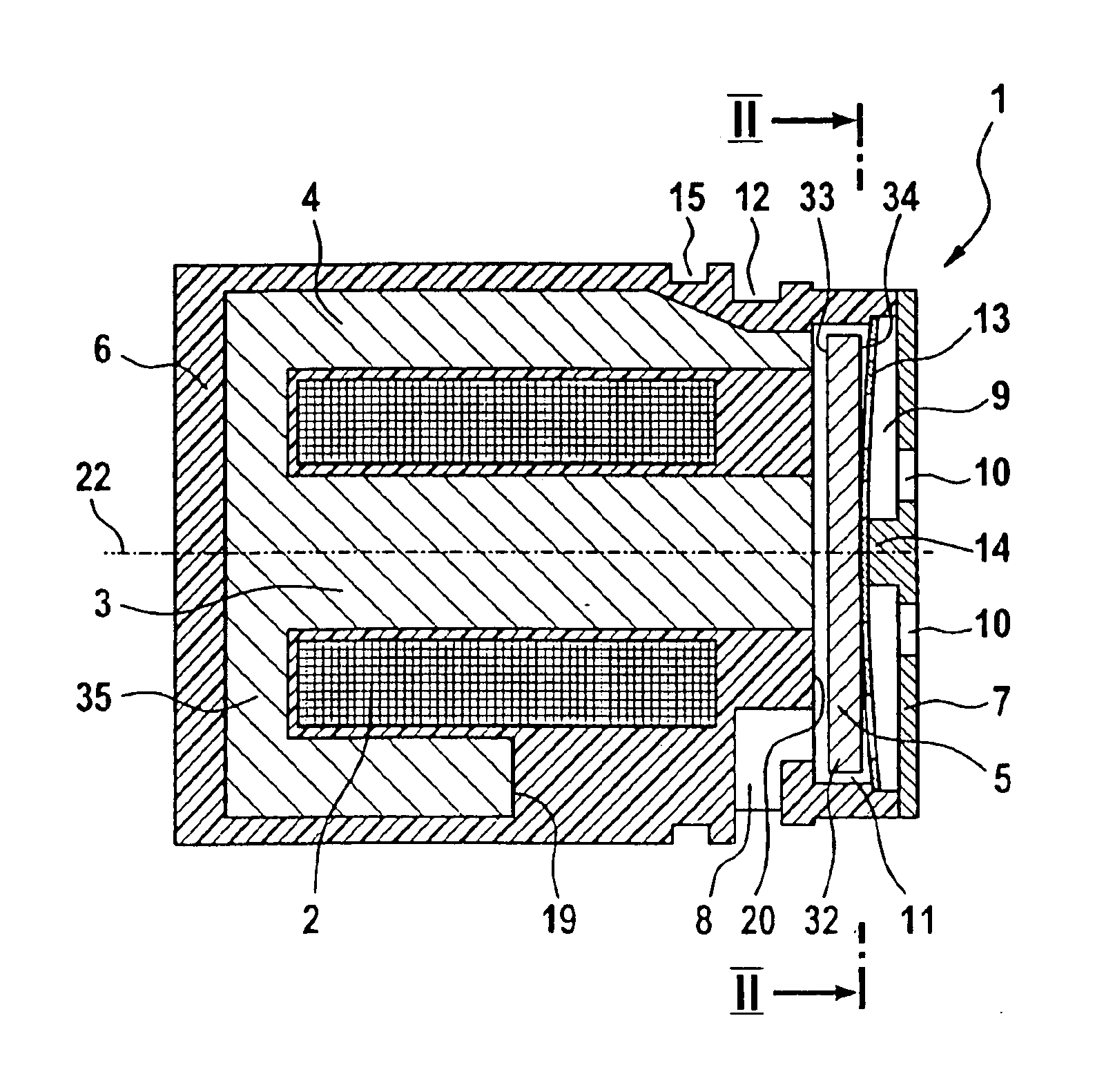
Figure 1 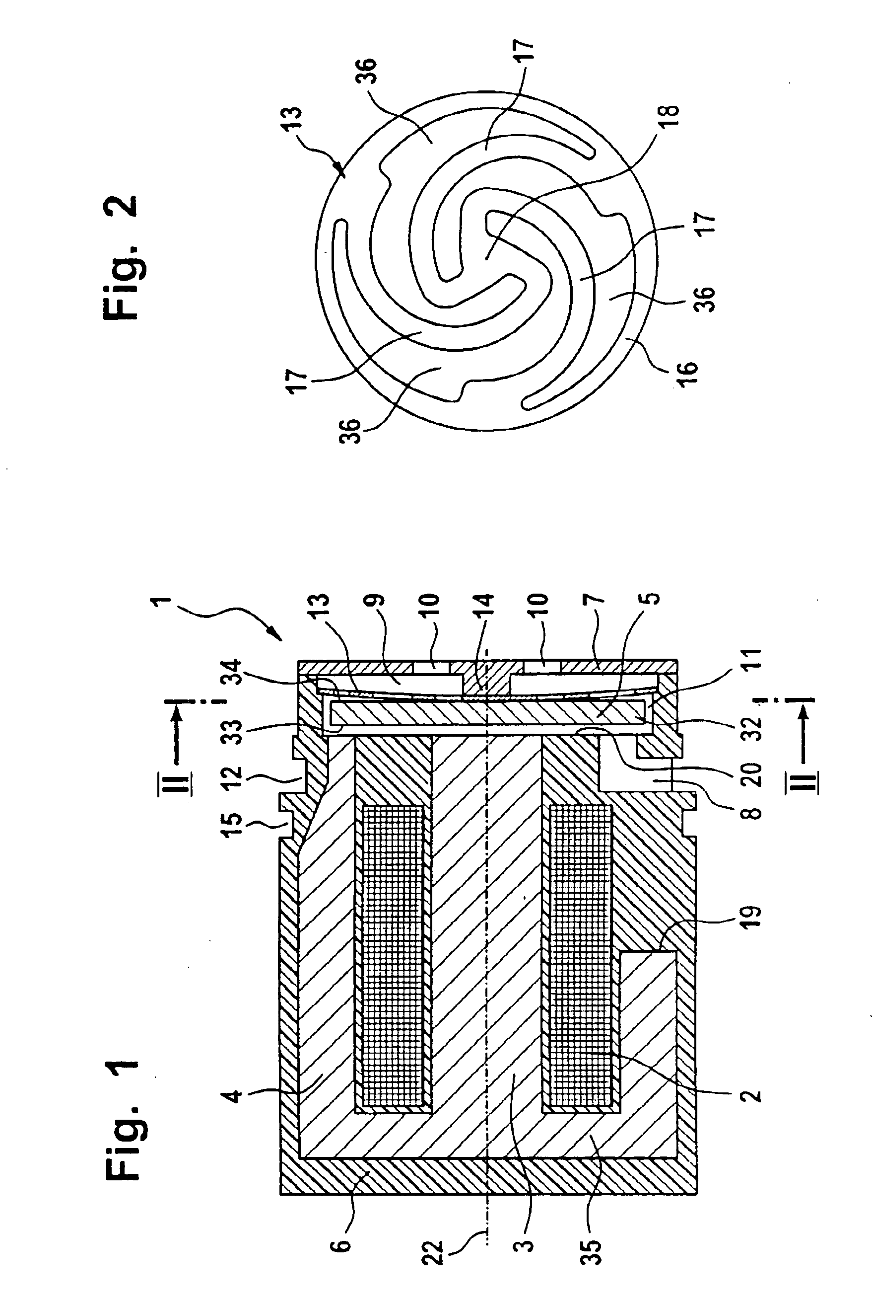
Figure 2 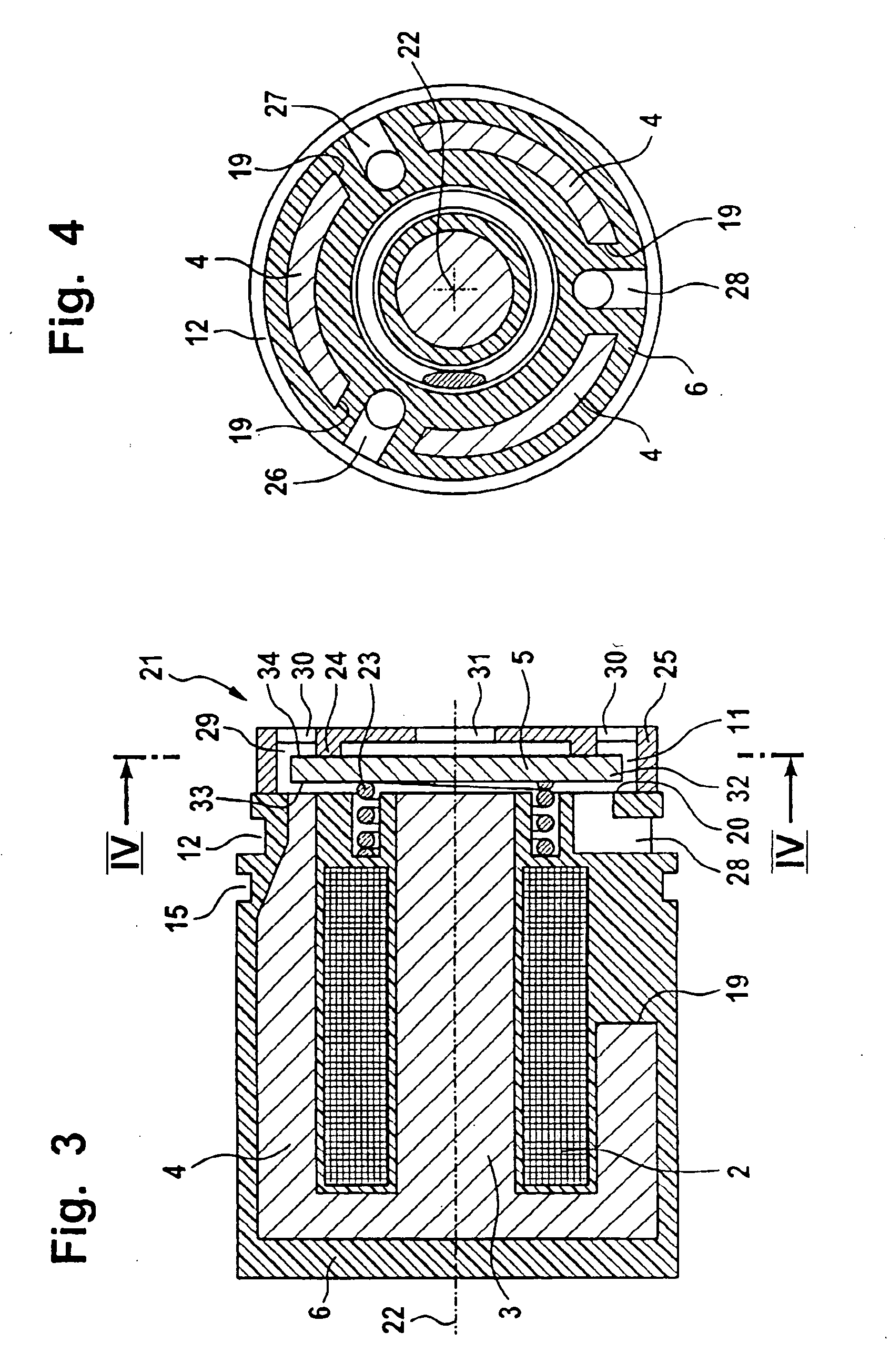
Figure 3
Abstract
Description
BACKGROUND OF THE INVENTION
[0001] German patent publication 201 04 770 discloses an electromagnetic valve having a coil in which an iron core is mounted. An armature plate is arranged on the iron core and carries a sealing nub. The iron core includes an axial bore which is closed by the sealing nub when there is a current flow in the coil. The axial bore in the iron core negatively influences the magnetic flux in the iron core. The force, which is available for pulling the armature plate, is thereby reduced. In order to be able to generate a sufficiently large force, a larger coil must be used. In this way, the entire structural size of the arrangement is increased. SUMMARY OF THE INVENTION
[0002] It is an object of the invention to provide an electromagnetic valve of the kind described above which can be manufactured with few parts and has a small structural size.
[0003] The electromagnetic valve of the invention includes: an iron core; a coil defining a longitudinal axis and bein...
Examples
Embodiment Construction
[0014] The electromagnetic valve 1 shown in FIG. 1 has a coil 2 in which an iron core 3 is arranged. The iron core is configured as one piece with a yoke 4 surrounding the coil 2 at its outer periphery. The coil 2 and the yoke 4 with the iron core 3 are arranged in a housing 6. The components are injection molded in the plastic which forms the housing 6. The yoke 4 is configured to have a pot-like shape and the base 35 of the yoke 4 is connected to the iron core 3. At the end of the yoke 4 facing away from the base 35, an armature plate 5 is movably journalled in the direction of the longitudinal axis 22 of the coil 2.
[0015] The housing 6 is closed by a housing cover 7 at the end facing away from the base 35 of the yoke 4. A center stop 14 is arranged on the housing cover 7 and limits the movement of the armature plate 5 in the direction of the longitudinal axis 22 of the coil.
[0016] The armature plate 5 is configured to have the shape of a circular disc and is journalled in the h...