
Circuit with variable capacitance and method for operating a circuit with variable capacitance
a technology of capacitance and circuit, which is applied in the direction of oscillator, pulse automatic control, angle modulation details, etc., can solve the problem of not being able to produce such a voltage control oscillator at a low price, large hardware expenditure, and short character tuning curve generated therefrom, so as to avoid complicated and thus cost-intensive switching, simple circuit engineering, and the effect of flatter and more linear characteristic capacitance curv
Patent Information
- Authority / Receiving Office
- US · United States
- Patent Type
- Applications(United States)
- Current Assignee / Owner
- Publication Date
- 2005-09-22
Smart Images
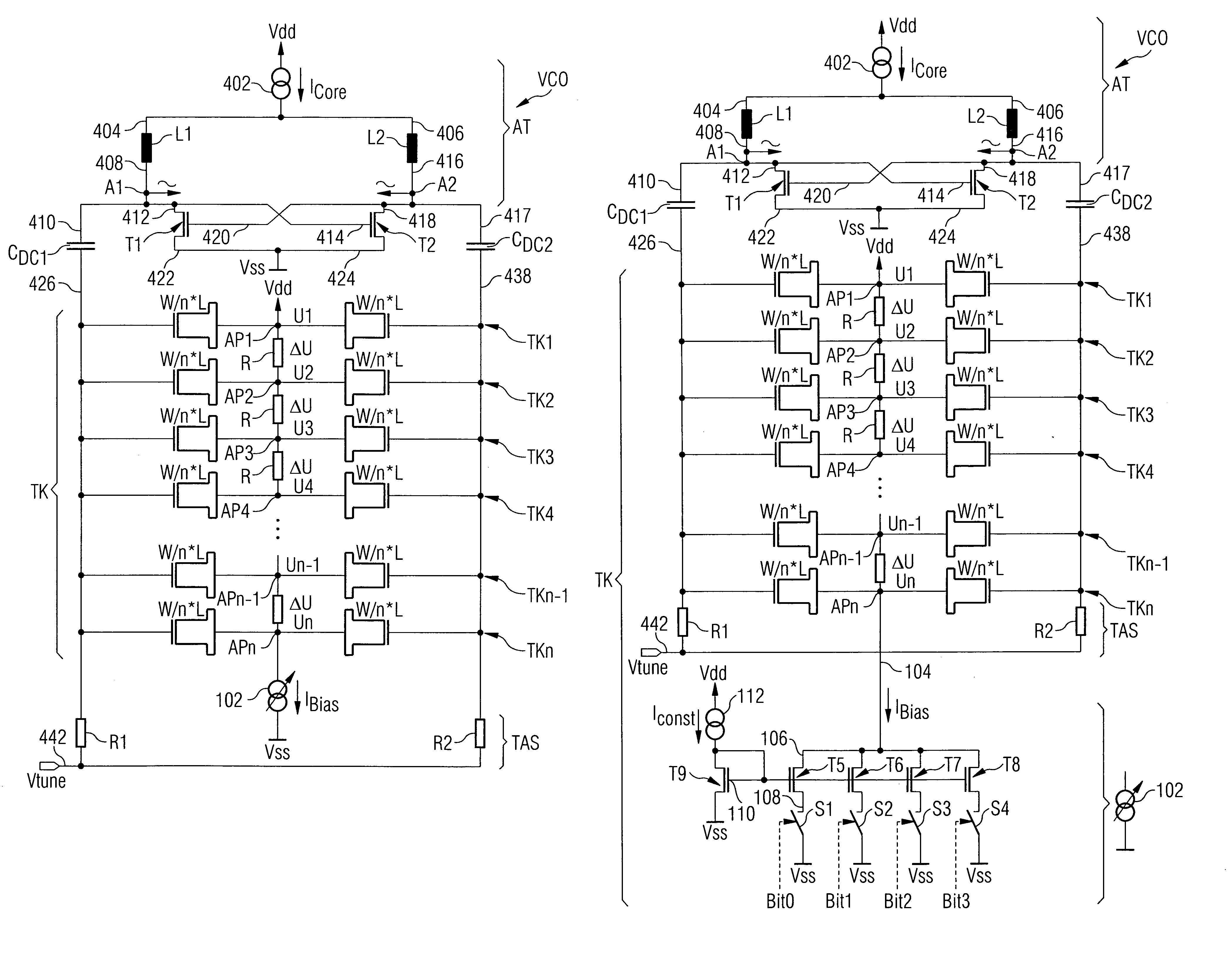
Figure 1 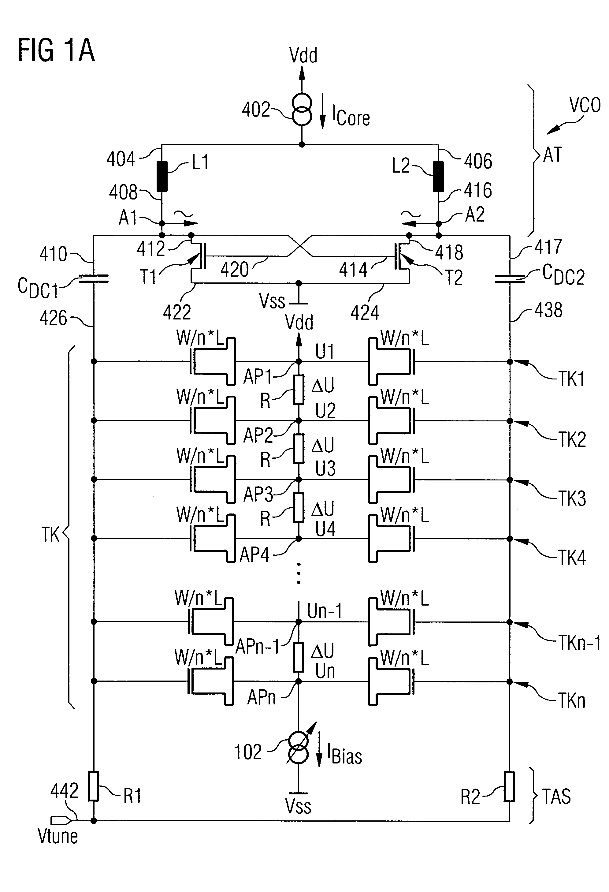
Figure 2 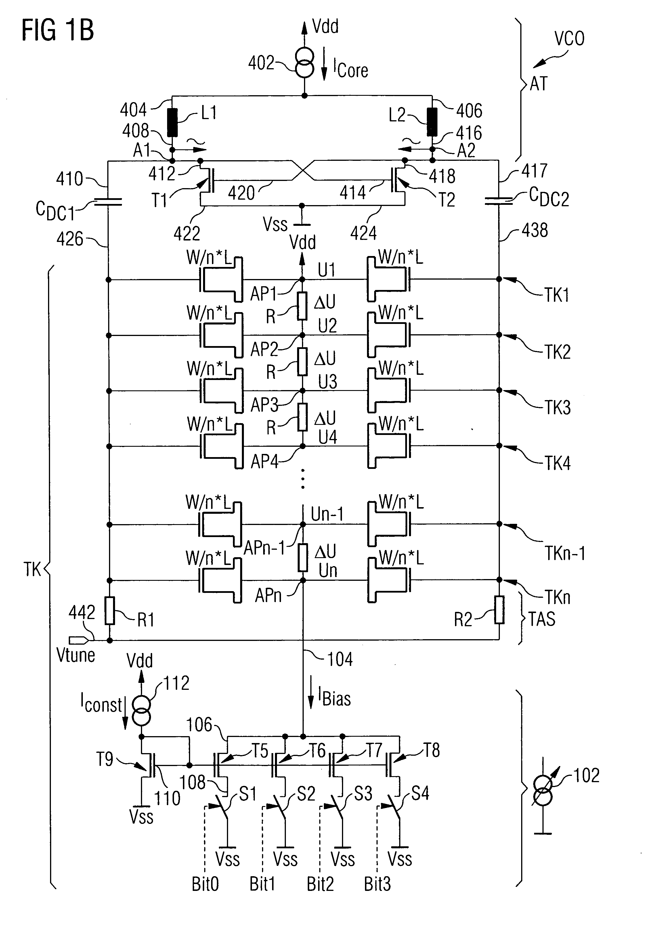
Figure 3
Abstract
Description
CROSS-REFERENCE TO RELATED APPLICATIONS
[0001] This application claims priority from German Patent Applications No. 10 2004 008 706.7, filed on Feb. 23, 2004, and No. 10 2004 008 701.6, filed on Feb. 23, 2004, which are incorporated herein by reference in their entirety. BACKGROUND OF THE INVENTION
[0002] 1. Field of the Invention
[0003] The present invention relates to a circuit with variable capacitance and a method for operating a circuit with variable capacitance, and, in particular, the present invention relates to an electronic circuit with variable capacitance whose transition behaviour between a minimum and a maximum saturation value is variable.
[0004] 2. Description of the Related Art
[0005] A conventional voltage controlled oscillator (VCO) in most cases has one or more characteristic tuning curves, wherein such a characteristic curve represents the relation between an applied tuning voltage Vtune and an oscillation frequency. An exemplary oscillator circuit for a convent...
Examples
Embodiment Construction
[0033] In the following description of the preferred embodiments of the present invention, equal or similar reference numbers are used for elements illustrated in the various drawings and acting similarly, wherein a repeated description of these elements is omitted.
[0034]FIG. 1A shows a circuit diagram of an embodiment of the exemplary oscillator circuit. The embodiment of the exemplary oscillator circuit essentially corresponds to the conventional oscillator circuit illustrated in the circuit diagram in FIG. 4. Unlike the conventional oscillator circuit illustrated in FIG. 4, the circuit diagram of the embodiment of the exemplary oscillator circuit according to FIG. 1A shows a plurality of partial capacitances TK1, TK2, TK3, TK4, . . . , TKn−1, TKn, which, each for itself, are constructed analogously to the partial capacitance TK illustrated in FIG. 4. The individual partial capacitances thus again comprise two auxiliary transistors each whose respective drain and source terminals...