
Jumper device and jumper assembly
Patent Information
- Authority / Receiving Office
- US · United States
- Current Assignee / Owner
- Publication Date
- 2006-06-08
- Estimated Expiration
- Not applicable · inactive patent
Smart Images
Figure 1 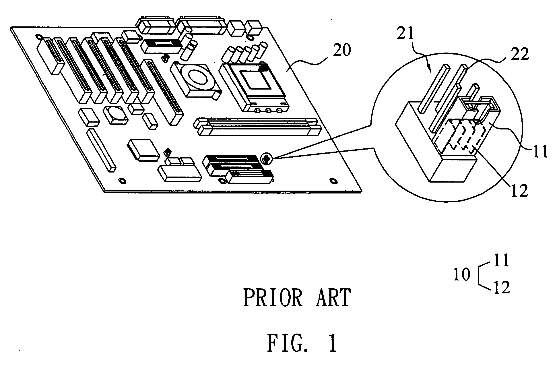
Figure 2 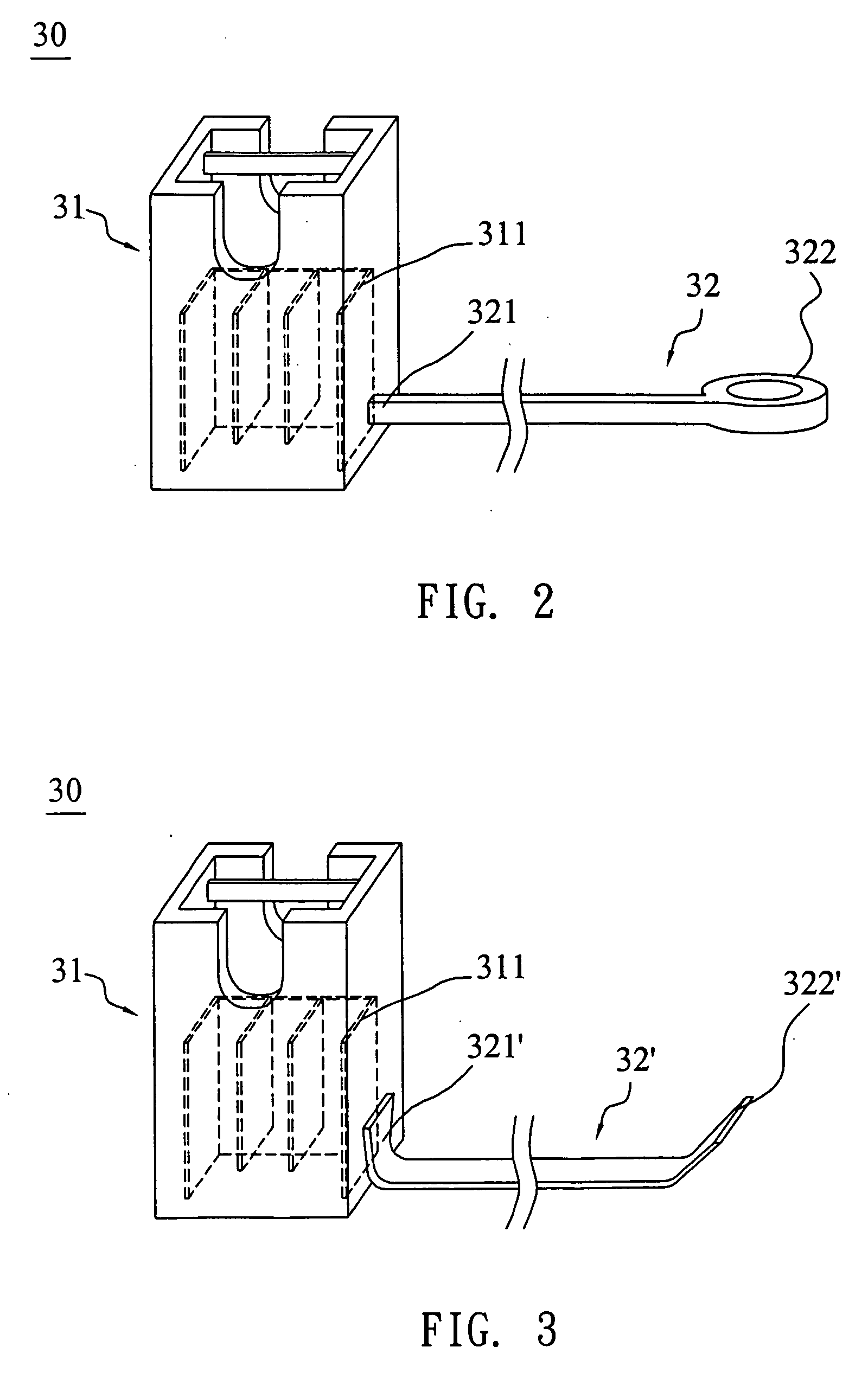
Figure 3
Abstract
Description
BACKGROUND OF THE INVENTION
[0001] 1. Field of Invention
[0002] The invention relates to a jumper device, and more particularly to a jumper device used in an electrical device.
[0003] 2. Related Art
[0004] A jumper is a tool for changing the circuit. In a computer, for example, a mainboard often has to fit with various electrical elements with different specifications, such as CPUs (Central Processing Units) with different speeds or different output voltages. If the manufacturer manufactures many kinds of mainboards to meet various conditions, the cost efficiency is low. It is possible to modify one trace on the mainboard to meet two different CPUs. In such a case, the jumper may be used in a simple way by only pulling up the jumper from the pin header of the mainboard, changing the position of the jumper, and then inserting the jumper into another position of the pin header. Consequently, the clock of the processor may be set, or the hard disk can be modified from a master to a sla...
Examples
Embodiment Construction
[0021] The present invention will be apparent from the following detailed description, which proceeds with reference to the accompanying drawings, wherein the same references relate to the same elements.
[0022] First, jumper devices according to a preferred embodiment of the invention will be described with reference to FIGS. 2 and 3.
[0023]FIG. 2 is a schematic illustration showing a jumper device according to the embodiment of the invention. The jumper device 30 includes a jumper 31 and a connecting member 32.
[0024] The casing of the jumper 31 is made of an insulation material such as a plastic material. The jumper 31 has a conductive jumper metal 311 inside the casing. When the jumper 31 is used, the jumper 31 is inserted by a pin header. At this time, the conductive jumper metal 311 of the jumper 31 can contact two pins of the pin header such that the pins are connected to each other through the conductive jumper metal 311 to form a close circuit (ON state), and the circuit of ...