
Power tool
a power tool and power technology, applied in the field of power tools, can solve the problems of high manufacturing and assembly cost, and achieve the effects of simplifying the switching mechanism, simplifying the construction of the seesaw lever, and complex linkages
Patent Information
- Authority / Receiving Office
- US · United States
- Patent Type
- Applications(United States)
- Current Assignee / Owner
- Publication Date
- 2006-06-29
- Estimated Expiration
- Not applicable · inactive patent
Smart Images
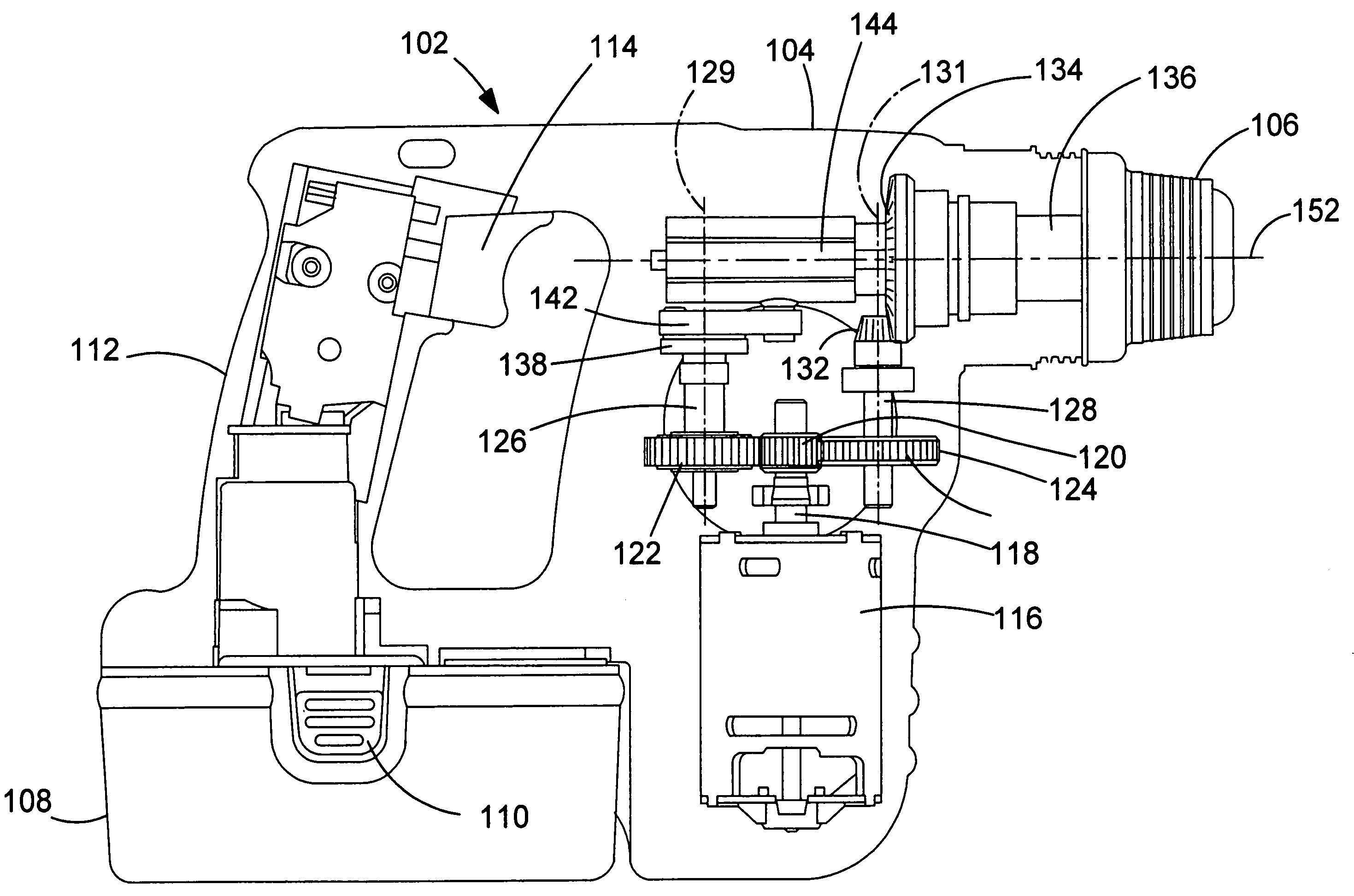
Figure 1 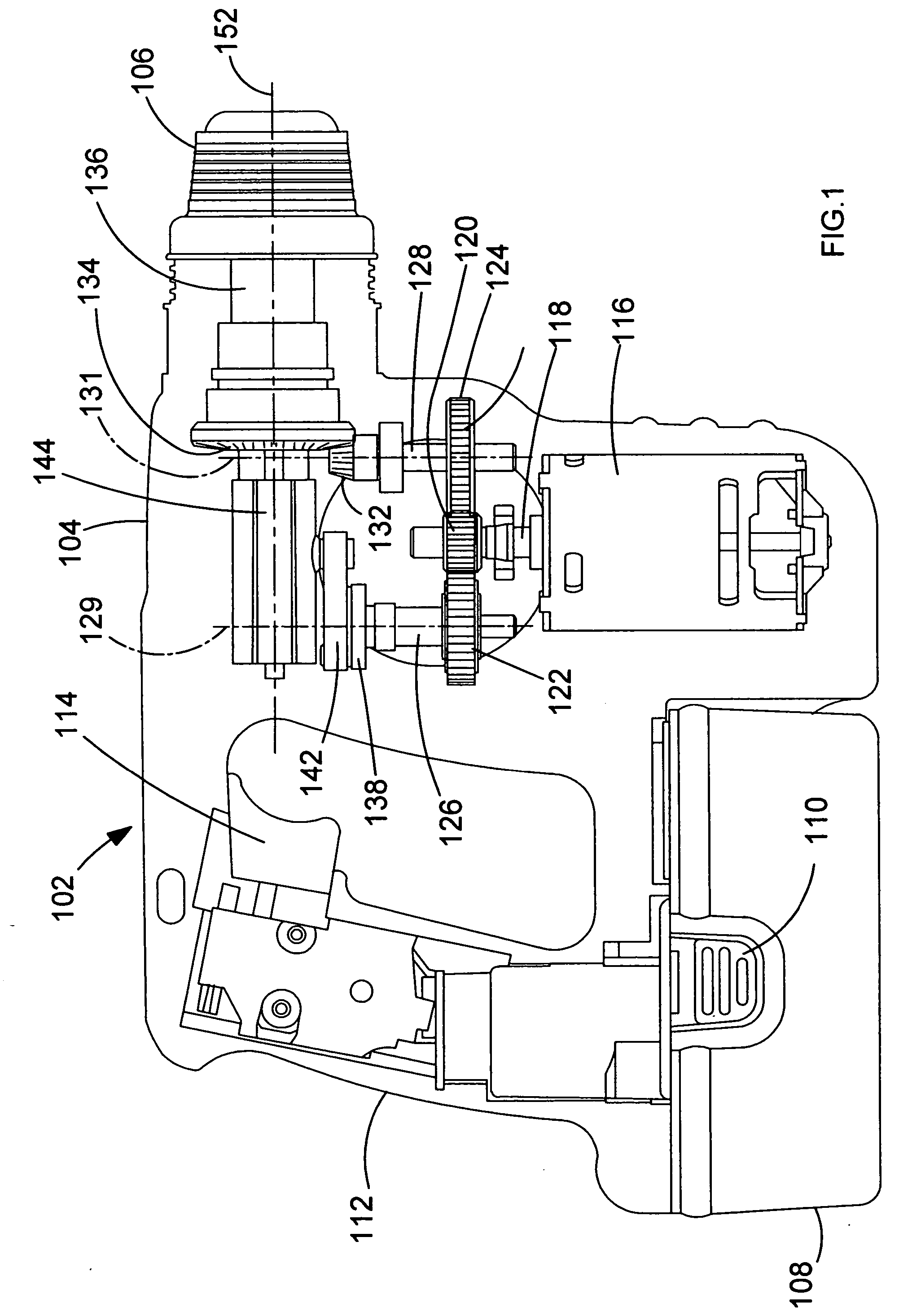
Figure 2 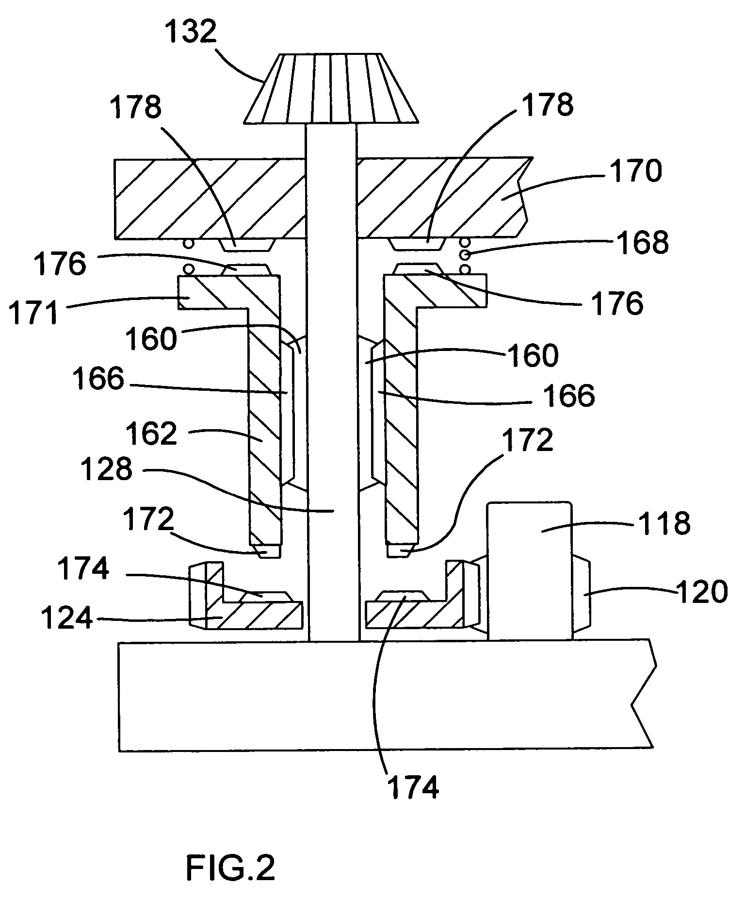
Figure 3
Abstract
Description
FIELD OF THE INVENTION
[0001] The present invention relates to a power tool. The invention relates particularly, but not exclusively, to a mode change mechanism for selecting a hammering mode, a rotary mode, and a combined hammering and rotary mode, and to a power tool incorporating such a mode change mechanism. BACKGROUND OF THE INVENTION
[0002] Hammers drills are power tools which can operate in one of three modes of operation. Generally, a hammer drill will have a tool bit which can be operated in a hammering mode, a rotary mode and a combined hammering and rotary mode.
[0003] Hammer drills also generally comprise a mode change mechanism which enables a user to select between the different modes of operation of the hammer drill.
[0004] European patent application EP0759342 discloses a hammer drill having a mode change mechanism comprising an axially slidable lock ring which is disposed on the spindle of the hammer drill. The rotational mode of the hammer drill is selected by rota...
Examples
Embodiment Construction
[0031] Referring to FIG. 1, a hammer drill shown generally by 102 comprises a housing 104 formed from at least two clamshell halves of durable plastics material, as will be understood by persons skilled in the art. Extending from a forward end of housing 104 is a chuck 106 or similar device for gripping a drill bit (not shown). A rechargeable battery pack 108 is detachably fixed to the bottom of the housing, and can be detached from the housing 104 by depressing clips 110 to release the battery pack for the purpose of recharging or exchange. The housing 104 comprises a handle portion 112 having a trigger switch 114. An electric motor 116 is disposed in the housing. The motor is electrically coupled to the battery pack via the trigger switch. The trigger switch is for selectively energising the motor to operate the hammer drill. An output shaft 118 extends from the motor 116. The output shaft 118 has a pinion 120 formed thereon. The pinion 120 meshes with a first gear 122 and a secon...