
Car-used lock with alerting function
a technology of alerting function and car locks, which is applied in the field of multifunctional car locks, can solve the problem of not being able to effectively prevent the thief from stealing the car, and achieve the effect of avoiding the busy line of the car owner's phon
Patent Information
- Authority / Receiving Office
- US · United States
- Current Assignee / Owner
- Publication Date
- 2007-09-13
- Estimated Expiration
- Not applicable · inactive patent
Smart Images
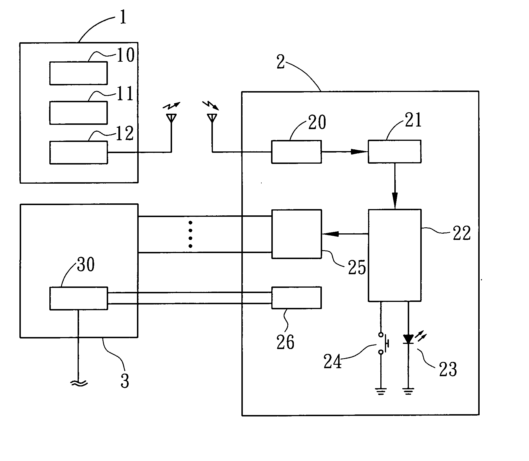
Figure 1 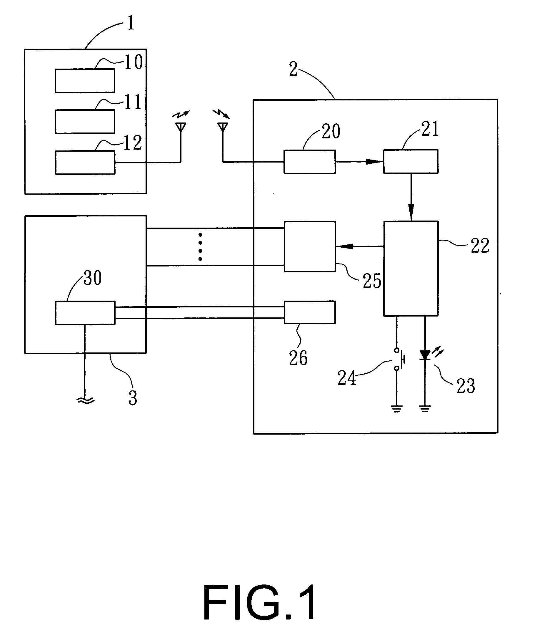
Figure 2 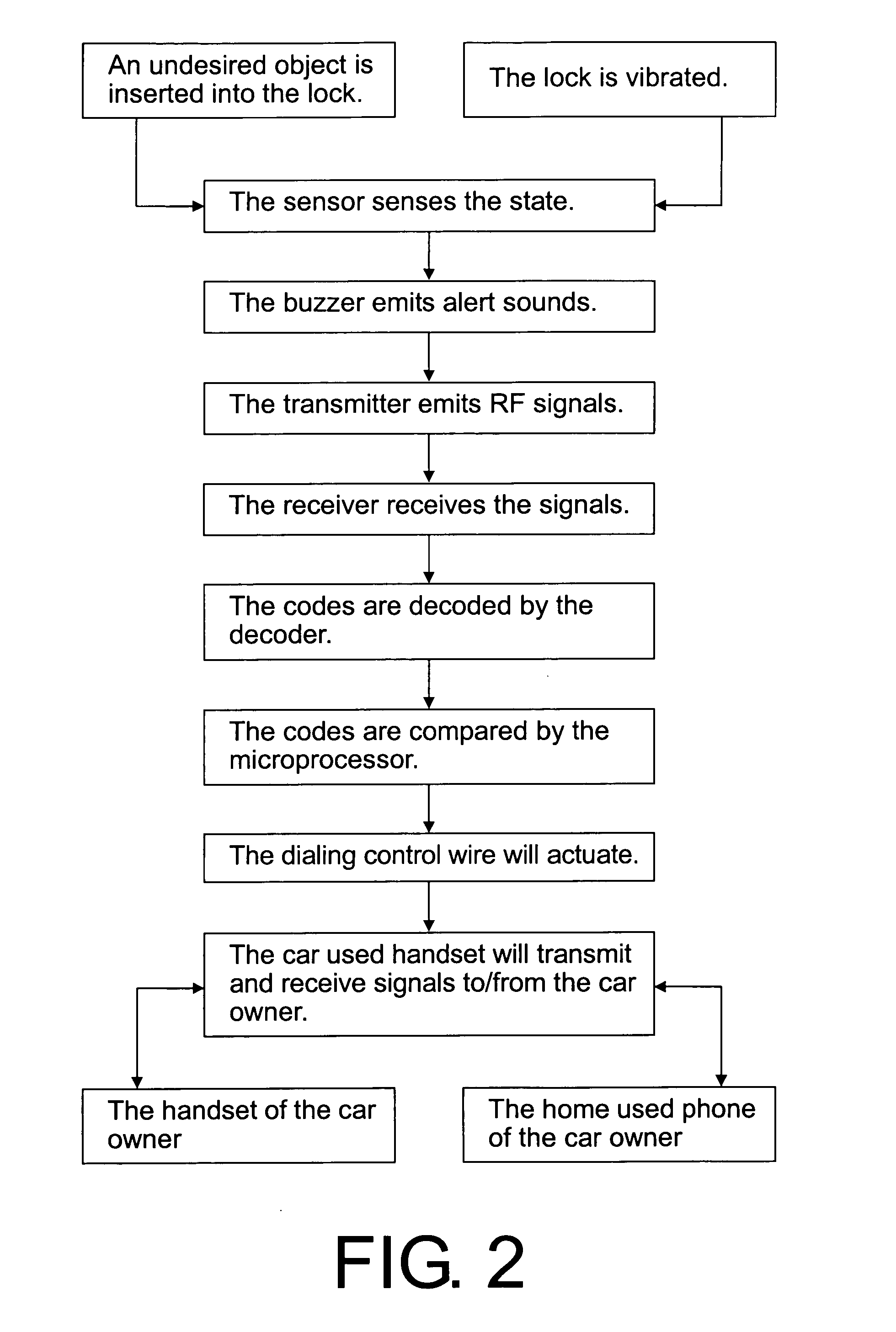
Figure 3
Abstract
Description
FIELD OF THE INVENTION
[0001] The present invention relates to car-used locks, and in particular to a multi-functional car lock, wherein the lock is effective in the thief-proof. The present invention has the affect of immediate alert and communication with legal frequency bands and power. The power source is from the car used handset. No additional battery is necessary. Furthermore, two sets of quick dialing numbers are used so that the line's busy of the car owner's phone can be avoided. BACKGROUND OF THE INVENTION
[0002] Currently door lock is assembled to a steering wheel of the car so that the thief cannot rotate the steering wheel. Or the door lock is assembled to a gear switch of a car so that the gear switch cannot be operated. Or the door lock is assembled the oil treadle so that the thief cannot trading the oil treadle to drive the car. However above-mentioned way cannot effectively prevent the thief to steal the car. SUMMARY OF THE INVENTION
[0003] Accordingly, the primar...
Examples
Embodiment Construction
[0008] In order that those skilled in the art can further understand the present invention, a description will be described in the following in details. However, these descriptions and the appended drawings are only used to cause those skilled in the art to understand the objects, features, and characteristics of the present invention, but not to be used to confine the scope and spirit of the present invention defined in the appended claims. Referring to FIG. 1, the elements of the present invention will be described herein.
[0009] A lock 1 is installed with a sensor 10, a buzzer 11 and a transmitter 12.
[0010] A receiving control device 2 receives signals from the transmitter 12. The receiving control device 2 is installed with a receiver 20, a decoder 21, a microprocessor 22, an indicator 23, a leaning key 24, a dialing control wire 25 and a power source 26. The receiver 20 serves to convert the high frequency signals emitted from the transmitter 12 into digital signals. The decod...