
Yoke for universal joint
a universal joint and yoke technology, applied in the direction of fastening means, yielding couplings, pipes, etc., can solve the problem of incomplete transmission of torque, achieve reliable coupling and fixed, and prevent noise from occurring, the effect of preventing transmission of torqu
Patent Information
- Authority / Receiving Office
- US · United States
- Patent Type
- Applications(United States)
- Current Assignee / Owner
- Publication Date
- 2008-01-17
Smart Images
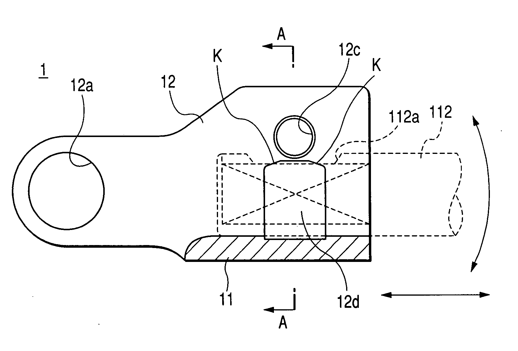
Figure 1 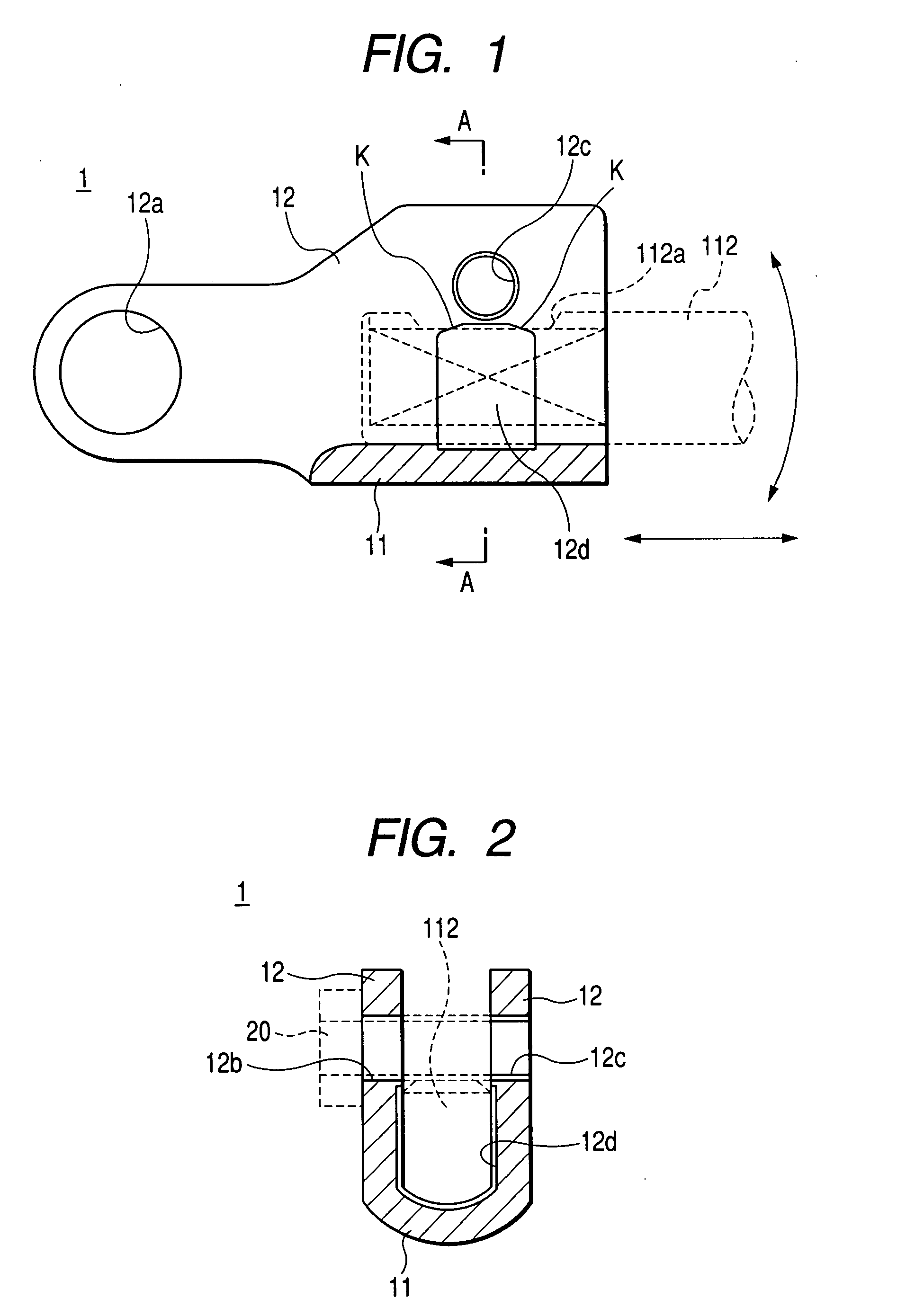
Figure 2 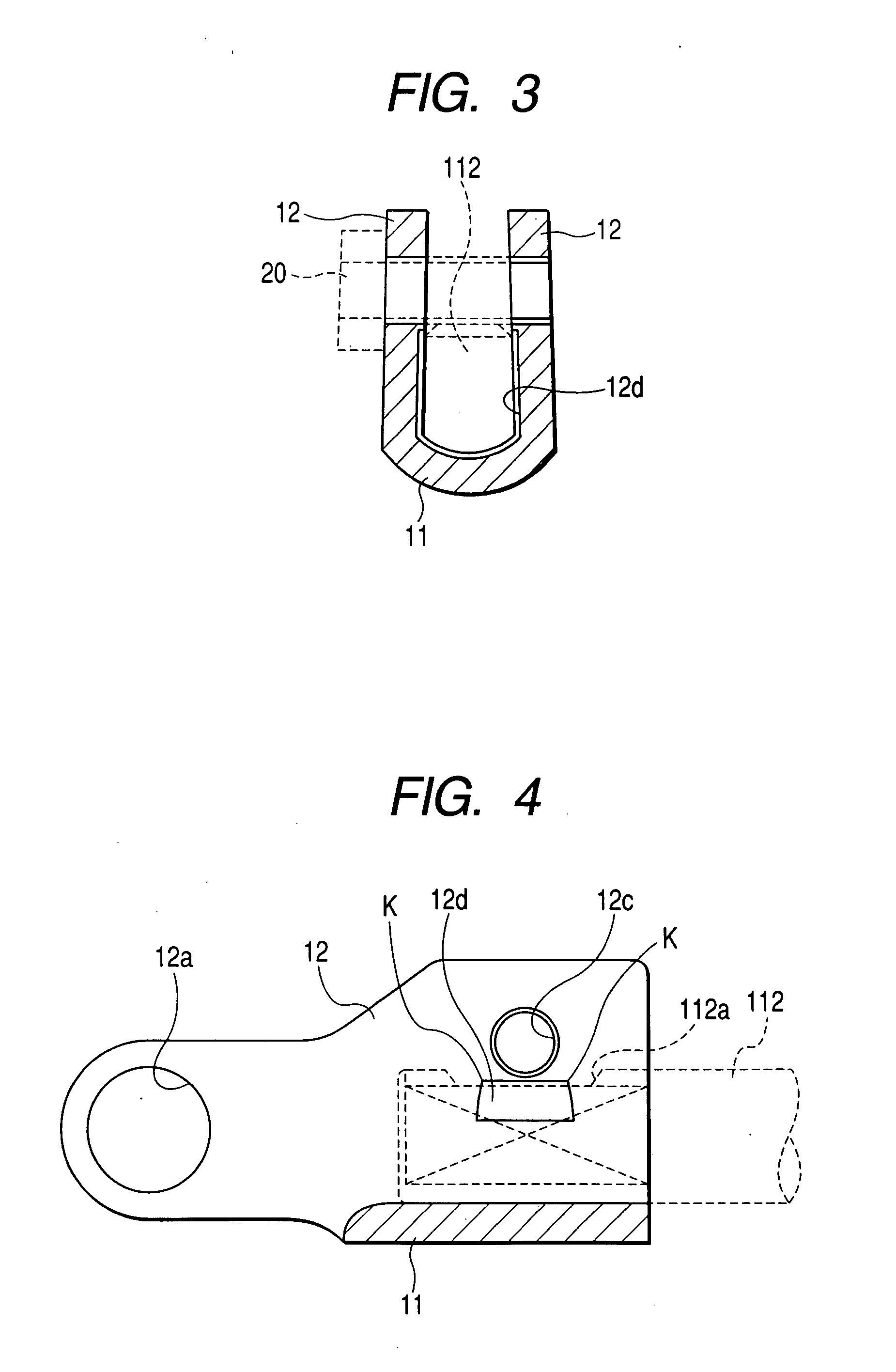
Figure 3
Abstract
Description
BACKGROUND OF THE INVENTION
[0001] The present invention relates to a yoke for universal joint including a base portion and a pair of opposed side walls which extend from the base portion so as to face each other at a distance. In the yoke, one end of a rotating shaft inserted between the opposed side walls is interposed and fixed by the base portion and the opposed side walls when fastening portions of the opposed side walls at the leading ends thereof are fastened by a fastener.
[0002] A universal joint 100 serves to connect two shafts, of which the shaft lines intersect at a certain angle, so as to transmit the torque of one shaft to the other shaft. As shown in FIG. 8, the universal joint 100 includes a cross joint 101, of which the shaft lines cross each other, and two yokes 102 and 103 (a first yoke 102 and a second yoke 103), which are respectively connected to both ends of the shafts composing the joint cross 101 so as to rock around the shaft lines and to which one ends of ...
Examples
Embodiment Construction
[0028] Hereinafter, a preferred embodiment of the present invention will be described with reference to accompanying drawings. FIG. 1 is a cross-sectional view illustrating a schematic construction of a yoke for universal joint according to an embodiment of the invention, and FIG. 2 is a cross-sectional view taken along line A-A of FIG. 1. In the following descriptions, the yoke 1 for universal joint of this embodiment shown in FIGS. 1 and 2 will be provided in place of the second yoke 103 shown in FIGS. 8 to 10. In the descriptions excluding the yoke 1, the same reference numerals will be attached, and the detailed descriptions thereof will be omitted.
[0029] The yoke 1 for universal joint (the second yoke) of this embodiment is formed of a material having lower hardness than the input shaft 112 of the steering gear. As shown in FIGS. 1 and 2, the yoke 1 for universal joint includes a base portion 11 and a pair of opposed side walls 12 which extend upward from the base portion 11 s...