
Near field communication antenna and mobile device
a technology of near field communication and mobile devices, applied in the direction of loop antennas, loop antennas with ferromagnetic cores, loop antennas, etc., can solve the problem that the relationship between communicable positions cannot be intuitively known, and achieve the effect of enhancing the directivity of communication direction, increasing reception sensitivity, and easy switching
Patent Information
- Authority / Receiving Office
- US · United States
- Patent Type
- Applications(United States)
- Current Assignee / Owner
- Publication Date
- 2008-10-02
- Estimated Expiration
- Not applicable · inactive patent
Smart Images
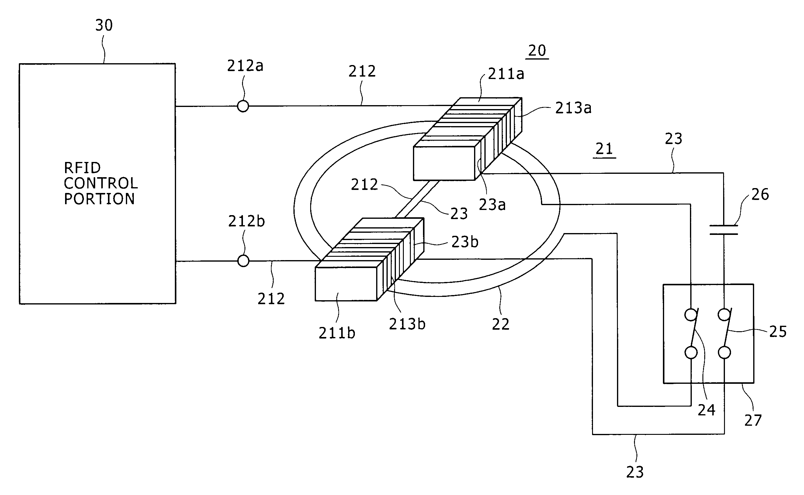
Figure 1 
Figure 2 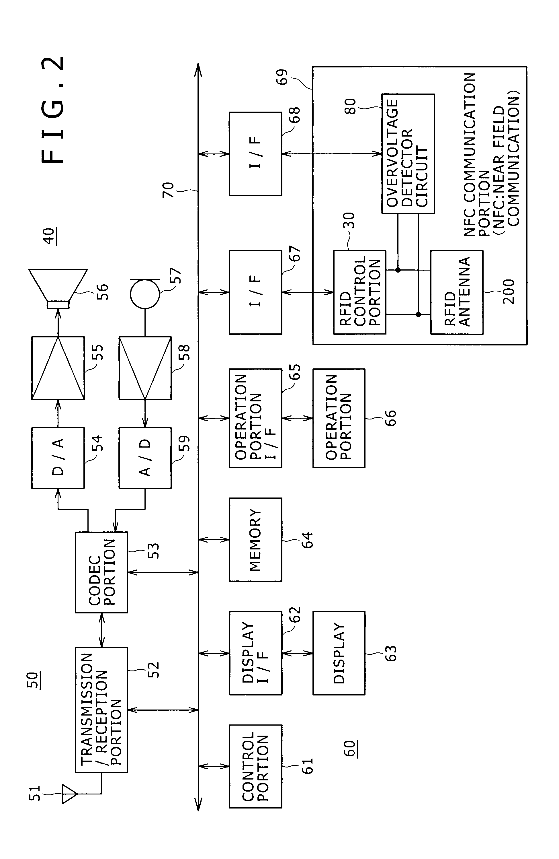
Figure 3
Abstract
Description
CROSS REFERENCES TO RELATED APPLICATIONS
[0001] The present invention contains subject matter related to Japanese Patent Application JP 2007-078966 filed in the Japanese Patent Office on Mar. 26, 2007, the entire contents of which being incorporated herein by reference.BACKGROUND OF THE INVENTION
[0002] 1. Field of the Invention
[0003] The present invention relates to a near field communication (NFC) antenna well suited for use in RFID (radio frequency identification, which is a generic name of contactless or proximity recognition techniques using electromagnetic waves) and a mobile device including an NFC communication portion and using the NFC antenna
[0004] 2. Description of the Related Art
[0005] Recently, an RFID function is mounted in a standard manner on mobile devices, such as mobile phones. In past and existing techniques, a loop antenna has been used as an antenna of an NFC communication portion to realize the RFID function.
[0006] Recently, however, miniaturization or compactness and...
Examples
first embodiment
[0050]FIG. 1 is a view showing an example of the configuration of an RFID NFC communication portion. The configuration includes an NFC antenna 20 (or, “RFID antenna 20,” herebelow) of the embodiment and an RFID control portion 30. In the present embodiment, the RFID control portion 30 (RFID: radio frequency identification) is formed from an RFID LSI.
[0051]The RFID antenna 20 is configured as an assembly (or, “antenna assembly”) including a ferrite antenna 21, a loop coil 22, and a manual switching device.
[0052]The ferrite antenna 21 has a bisectional configuration, similarly as in the Related Art example. More specifically, the ferrite antenna 21 of the embodiment is formed in the manner that a single copper wire 212 is wound on each of two ferrite cores 211a and 211b. Thereby, respective coils 213a and 213b are formed.
[0053]Alternatively, the ferrite antenna 21 can be configured such that the respective antenna coils 213a and 213b are formed in the manner that the copper wire 212 f...
second embodiment
[0067]As described above, the manual switching device for switching between the directivity characteristics (or, “directivity-characteristic switching device,” herebelow) is used in the first embodiment. However, the manual switch can be replaced with an electronic switch, thereby enable automatic control of the switching between the directivity characteristics. In this case, a function of a device for performing the automatic switching control of the electronic switch is included in a control portion of a mobile device including an NFC antenna of a second embodiment.
[0068]The following describes the NFC antenna of the second embodiment in which the electronic switch is used as the directivity-characteristic switching device. The NFC antenna of the second embodiment will be described together with a mobile device of the second embodiment employing the NFC antenna.
[0069]FIG. 2 is a block diagram showing an example of the configuration of a mobile phone terminal 40 as an example of th...
other embodiments and modified examples
[0094]As described above, in the example of the configuration shown in FIG. 3, the overvoltage detector circuit 80 is provided in the NFC communication portion 69. However, the configuration may be such that the voltage obtained in the region between the ends of the coils 213a and 213b is converted to a digital signal and is supplied to the control portion 61 through the system bus 70. Further, the function of the overvoltage detector circuit 80 can be provided in the form of a configuration of a software process executable by the MPU of the control portion 61.
[0095]The respective one of the embodiments and examples has been described with reference to the example case in which the example of the mobile device is the mobile phone terminal. However, the present invention can even be adapted to any mobile devices other than the mobile phone terminal inasmuch as the devices have an NFC communication portion such as described above.
[0096]Further, in the example shown in FIG. 3, the FET ...