

Combustion Type Power Tool
Patent Information
- Authority / Receiving Office
- US · United States
- Current Assignee / Owner
- Publication Date
- 2009-04-09
- Estimated Expiration
- Not applicable · inactive patent
Smart Images
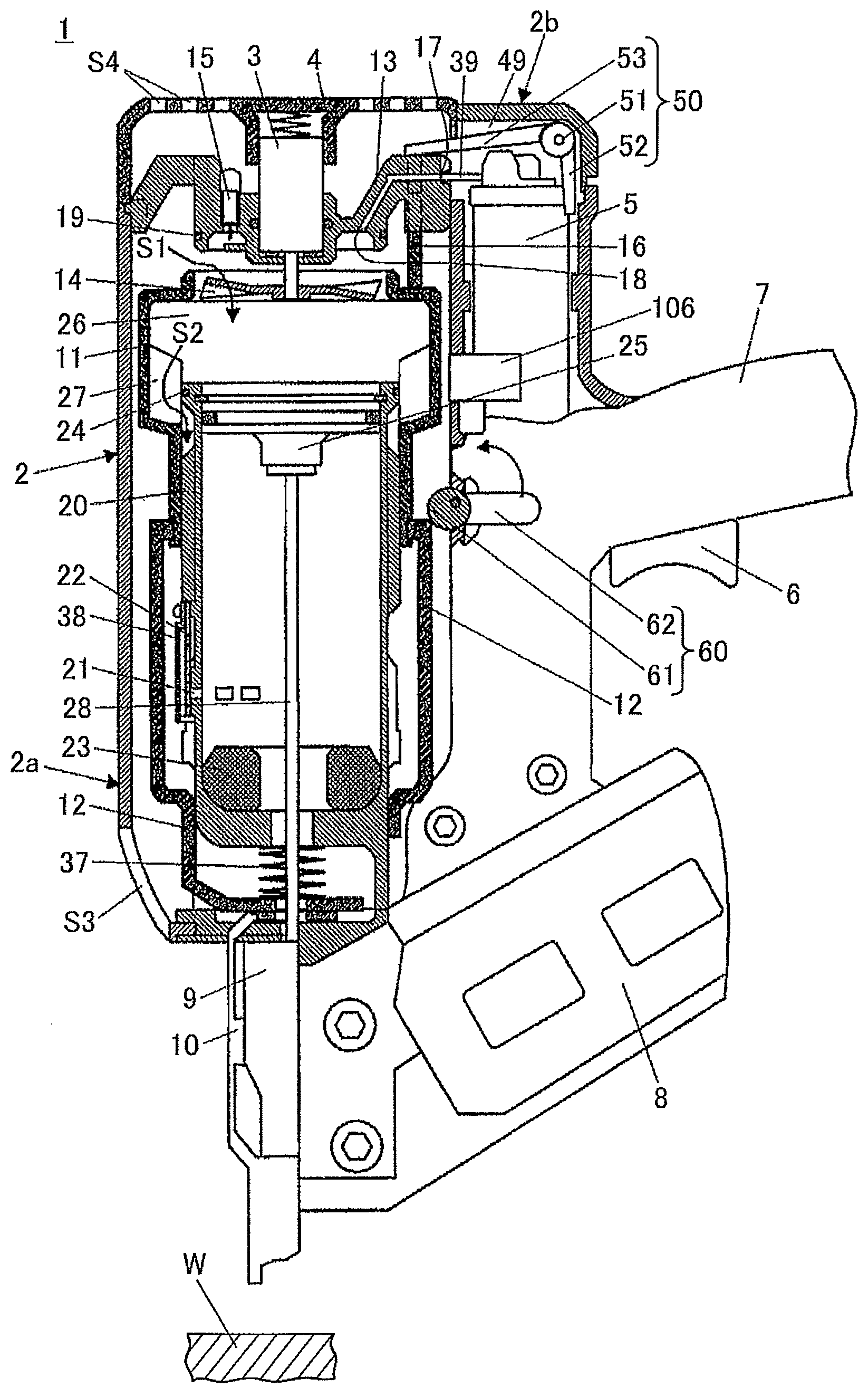
Figure 1 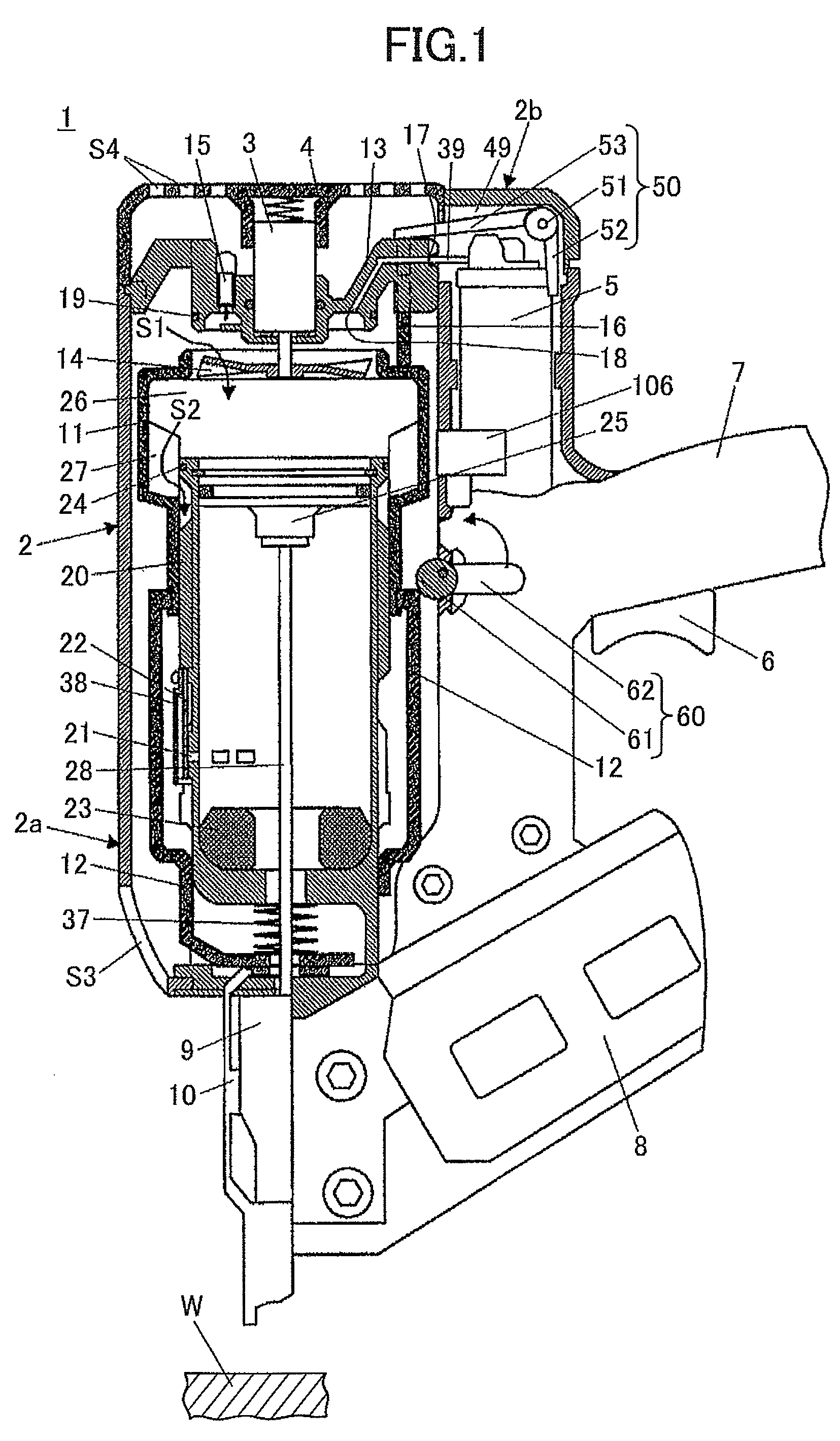
Figure 2 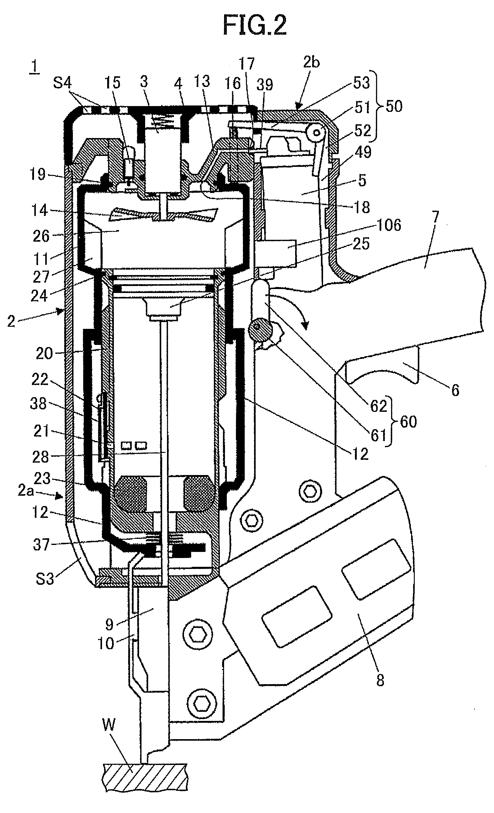
Figure 3
Abstract
Description
TECHNICAL FIELD
[0001] The present invention relates to a combustion type power tool, and more particularly, to a type thereof in which liquefied gas filled in a gas canister is injected into a combustion chamber, mixed with air and ignited, thereby generating driving force for moving a piston to drive fasteners such as nails, rivets and staples and the like.BACKGROUND ART
[0002] As shown in FIG. 4, a portable combustion type power tool 90 generally includes a housing 2, a cylinder 20, a piston 25, a driver blade 28, a chamber head 13, a combustion chamber frame 11, a canister housing 49, a fan 14, an ignition plug 15, and a trigger switch 6. The housing 2 contains various components. The cylinder 20 is provided in the housing 2. The piston 25 is slidably movable in the cylinder 20 in an axial direction thereof. The driver blade 28 is fixed to the piston 25 and drives fasteners into a workpiece W as the piston 25 moves. The chamber head 13 is spaced from an end of the cylinder 20, and i...
Examples
Embodiment Construction
[0080]A combustion type power tool according to one embodiment of the present invention will be described with reference to FIGS. 1 through 3. In the drawings like parts and components are designated by the same reference numbers and will not be described repeatedly. Similarly, the components identical in function to those of the conventional combustion type power tool shown in FIG. 4 and FIG. 5 are designated by the same reference numbers. Further, the direction in which nails (fasteners) are driven by the combustion type power tool will be referred to as “lower” or “lower portion”, and the direction opposite to this direction will be referred to as “upper” or “upper portion” for the sake of convenience. The embodiment pertains to a nail gun that is one of the typical examples of the combustion type power tool.
[0081]An overall configuration of nail gun 1 will be described. As shown in FIG. 1, a nail gun 1 includes a housing 2 that constitutes an outer frame. The housing 2 includes ...