
Apparatus and Method for Sensing a Time Varying Ionic Current in an Electrolytic System
a technology of electrolysis and apparatus, applied in the field of electrolysis sensing systems, can solve the problems of high sensitivity of electrolysis, and high cost, and achieve the effects of reducing capacitance, reducing system internal noise, or current noise, and increasing sensitivity
Patent Information
- Authority / Receiving Office
- US · United States
- Patent Type
- Applications(United States)
- Current Assignee / Owner
- Publication Date
- 2009-08-06
Smart Images
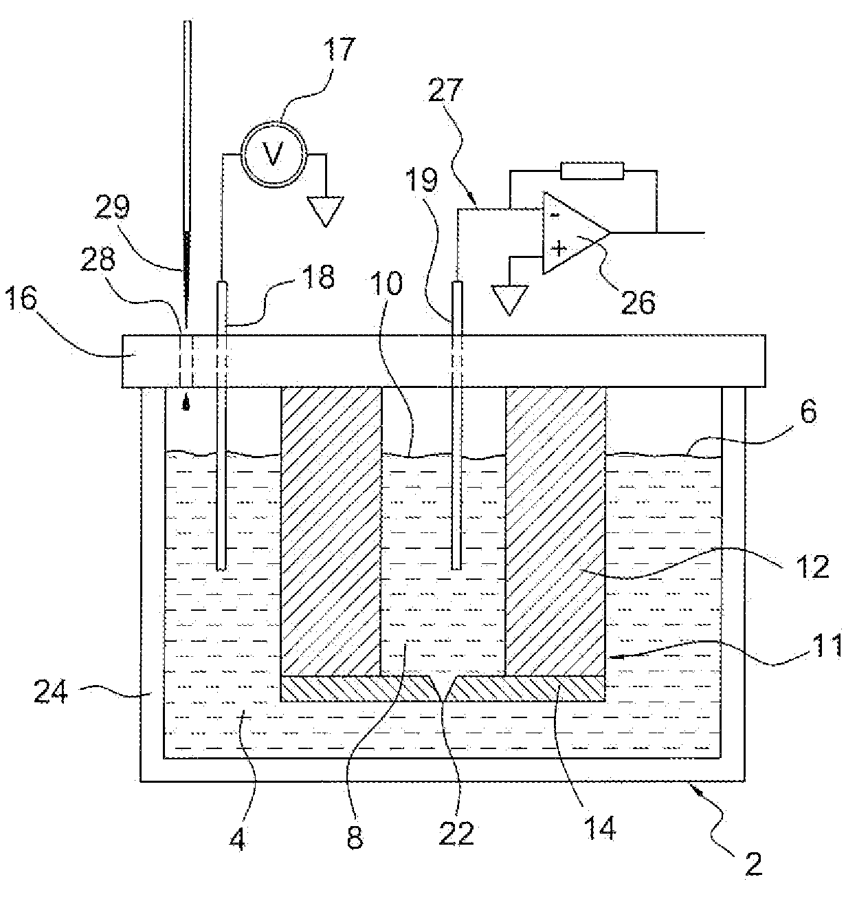
Figure 1 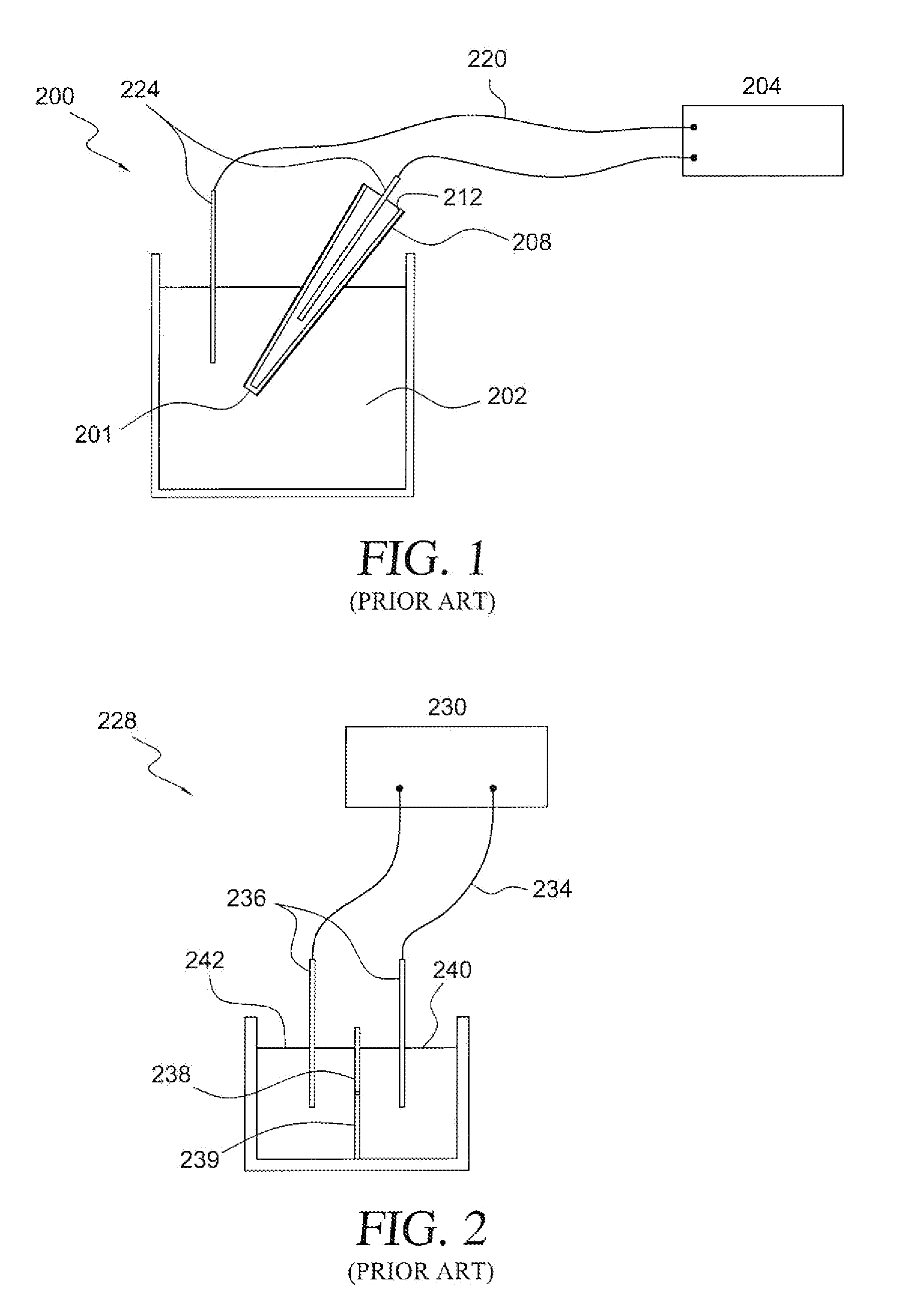
Figure 2 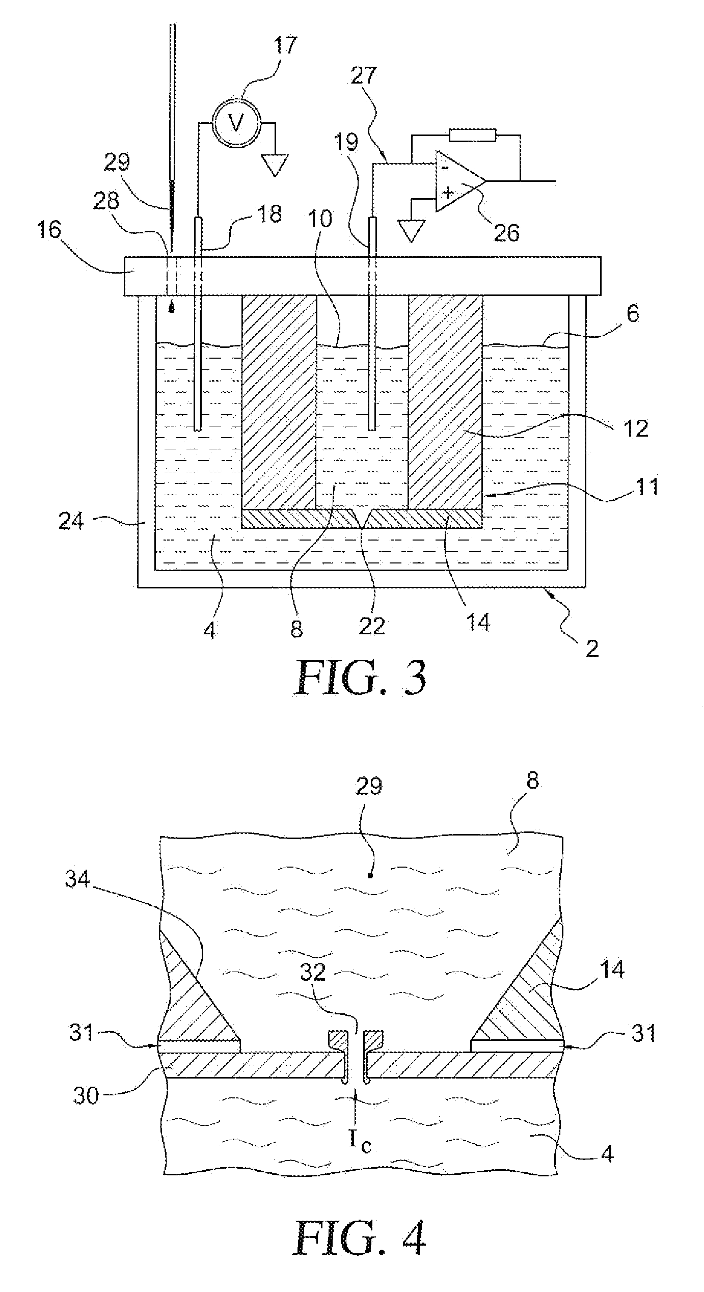
Figure 3
Abstract
Description
CROSS-REFERENCE TO RELATED APPLICATION
[0001] The present application represents a National Stage application of PCT / US2007 / 011257 filed May 10, 2007 entitled “Apparatus and Method for Sensing a Time Varying Ionic Current in an Electrolytic System”, and claims the benefit of U.S. Provisional Patent Application Ser. No. 60 / 813,712 filed Jun. 15, 2006 entitled “System for Improved Ion Channel Recordings and Related Measurement of Objects and Analytes in Solution.”BACKGROUND OF THE INVENTION
[0002] 1. Field of the Invention
[0003] The present invention pertains to the art of electrolytic sensing systems, and more specifically, to an apparatus and method for sensing a time varying ionic current in an electrolytic environment having improved sensitivity and bandwidth.
[0004] 2. Discussion of the Prior Art
[0005] The measurement of the electrical conductivity of small fluid regions is of importance in many applications. For example, small particles, such as viruses, suspended in a fluid can be coun...
Examples
first embodiment
[0044]Another possible configuration is for membrane 30 to be located on the inside of substrate 14, i.e. within the sensing volume 8, rather than electrolyte bath 4. This embodiment relates to an apparatus 2′ shown in FIG. 5, which is a structure especially applicable to producing an array of sensing elements in a solid material such as a silicon wafer. It uses the bulk of the solid material (e.g. Si) to provide a thick wall barrier 12′ with a base 40, such as PDMS, on the bottom of barrier 12′ to create a small fill line 42 to allow access to a sensing volume 8′. An ion channel (not shown in FIG. 5 but corresponding to ion channel 32 of the first embodiment) is inserted into a membrane 30′ from a bath side 4′ via a nanopore or orifice 22′ in a barrier 12′. If desired, an electrophoretic or conducting ring 48 is made on barrier 12′ around the orifice 22′ region, and is raised to a desired potential in order to provide an electrostatic force to aid in channel addressing. One benefit...
embodiment 2
[0049]A method of utilizing a continuous sampling embodiment 2″ of the present invention will now be discussed with reference to FIG. 9. System 2″ includes an electrolyte bath or fluid delivery element 104 and an electrolyte bath 108 provided with an electrolyte 110. Fluid delivery element 104 is separated from electrolyte bath 108 by a structure 111 comprised of a thick wall barrier 112 and a substrate 114. Additionally, a mounting substrate 116 extends across the top of electrolyte bath 108. Measurement electrodes 118 and 119 extend into fluid delivery element 104 and electrolyte bath 108, respectively. Substrate 114 contains an orifice 122. Recording electronics 126 are connected to electrode 119 by a conductor wire 127. A voltage source 117 is connected to bath electrode 118 and referenced to the system electrical ground. Delivery element 104 is attached to substrate 114 in a fluid-tight manner and contains a fluid-filled channel 154, which passes over orifice 122 for the purpos...