
Four quadrant mosfet based switch
Patent Information
- Authority / Receiving Office
- US · United States
- Current Assignee / Owner
- Publication Date
- 2010-07-15
- Estimated Expiration
- Not applicable · inactive patent
Smart Images
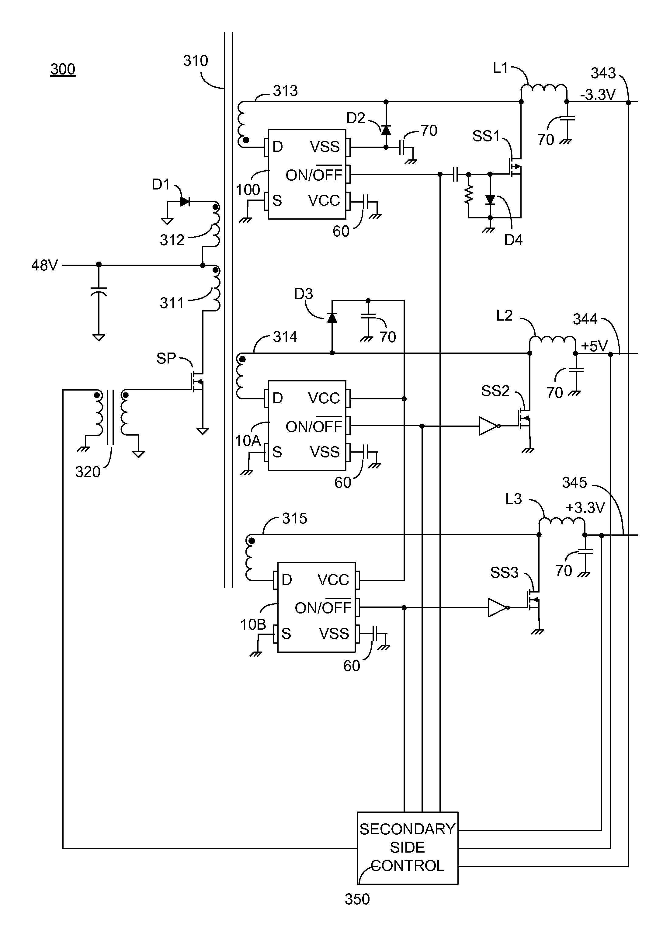
Figure 1 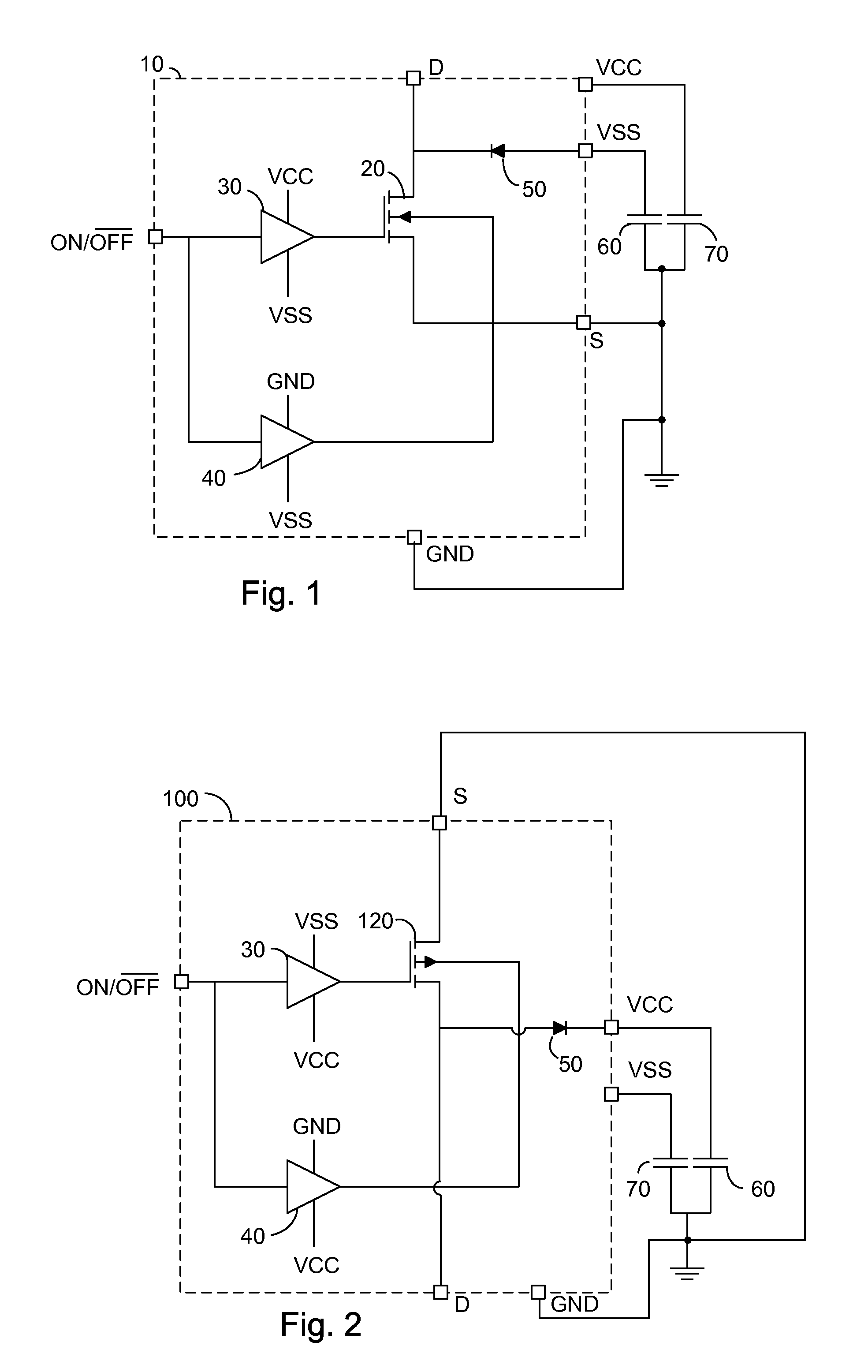
Figure 2 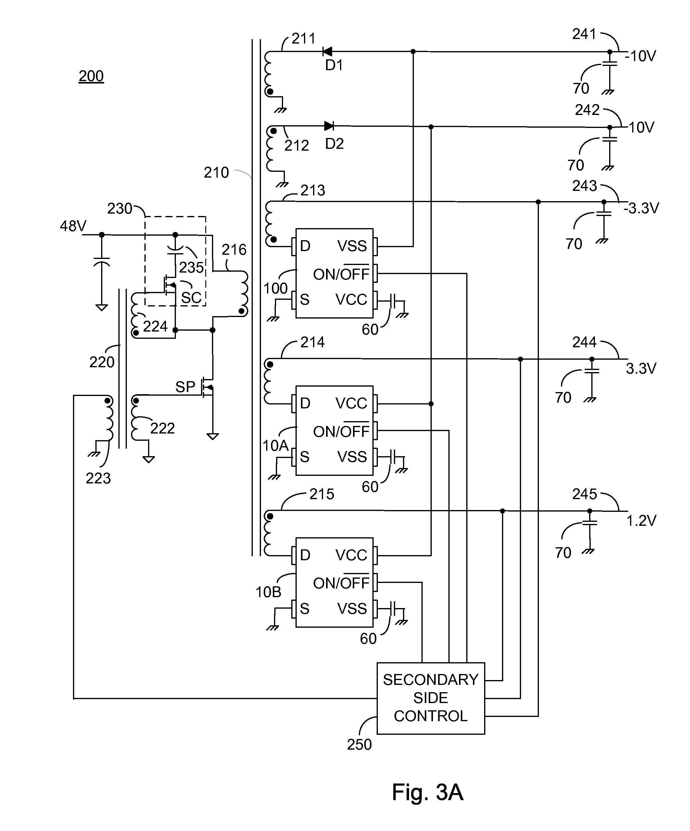
Figure 3
Abstract
Description
CROSS-REFERENCE TO RELATED APPLICATIONS
[0001] This application claims priority from U.S. Provisional Patent Application Ser. No. 61 / 145,040 filed Jan. 15, 2009, entitled “Four Quadrant MOSFET Based Switch”, the entire contents of which is incorporated herein by reference.TECHNICAL FIELD
[0002] The present invention relates to the field of electronically controlled switches, and more particularly to a MOSFET based electronically controlled switch arranged to block current in both directions when open.BACKGROUND OF THE INVENTION
[0003] A metal oxide semiconductor field effect transistor (MOSFET) is essentially a four terminal device: gate, drain, source and body. In almost all conventional MOSFETs the body is permanently internally attached to the source, and only three terminals are brought out for connection to other circuit elements. An N-Channel MOSFET, often written NMOSFET, will not block positive current flow from the source to the drain, irrespective of the gate voltage, if the dra...
Examples
Example
[0018]Before explaining at least one embodiment of the invention in detail, it is to be understood that the invention is not limited in its application to the details of construction and the arrangement of the components set forth in the following description or illustrated in the drawings. The invention is applicable to other embodiments or of being practiced or carried out in various ways. Also, it is to be understood that the phraseology and terminology employed herein is for the purpose of description and should not be regarded as limiting.
[0019]FIG. 1 illustrates a high level schematic diagram of an integrated four quadrant NMOSFET based switch 10 with an associated limit voltage source constituted of a capacitor 60 and a capacitor 70. Integrated four quadrant NMOSFET based switch 10 comprises an NMOSFET 20, a pair of drivers 30 and 40, and a unidirectional electronic valve 50. Integrated four quadrant NMOSFET based switch 10 further comprises a plurality of terminals denoted r...