
Linear vibration motor
Patent Information
- Authority / Receiving Office
- US · United States
- Current Assignee / Owner
- Publication Date
- 2011-01-06
- Estimated Expiration
- Not applicable · inactive patent
Smart Images
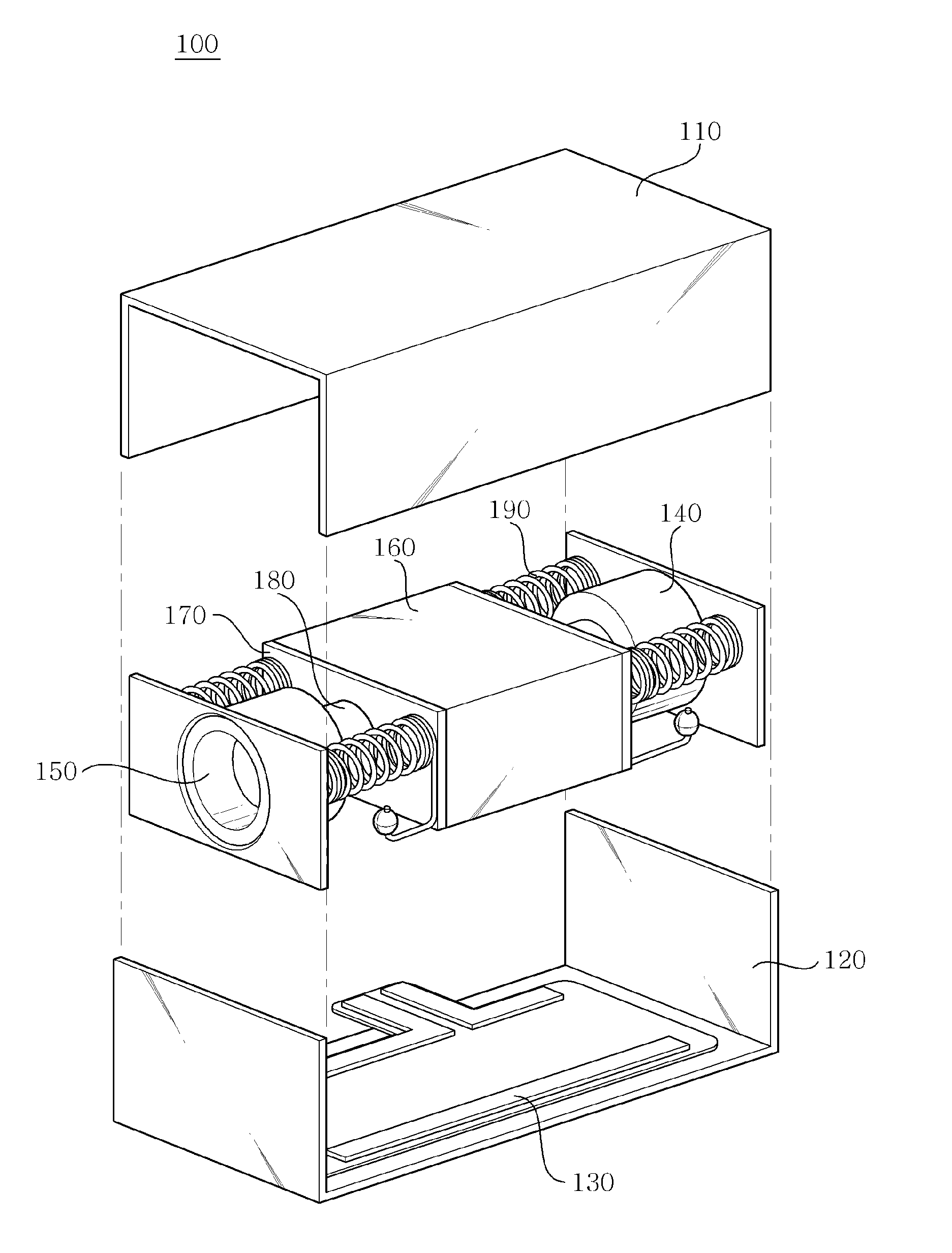
Figure 1 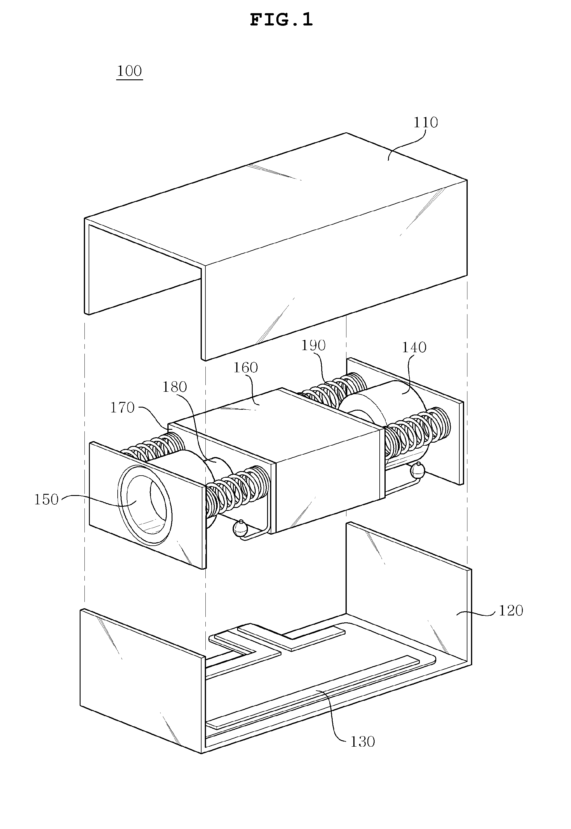
Figure 2 
Figure 3
Abstract
Description
CROSS REFERENCE TO RELATED ED APPLICATION(S)
[0001] This application claims the benefit of Korean Patent Application No. 10-2009-0059858, filed on Jul. 1, 2009, entitled “LINEAR VIBRATION MOTOR”, which is hereby incorporated by reference in its entirety into this application.BACKGROUND OF THE INVENTION
[0002] 1. Technical Field
[0003] The present invention relates generally to a linear vibration motor and, more particularly, to a linear vibration motor, in which a bearing is provided on an extension part of a spring coupling a motion part and a stationary part of the motor with each other, or a ball is provided on a protruding part of a yoke, thus minimizing friction and abrasion between adjacent parts when the motor is in operation, minimizing noise caused by the friction and abrasion thereof, and vibrating in a horizontal direction.
[0004] 2. Description of the Related Art
[0005] The most important function of a receiving device, the representative example of which is a mobile phone, is a r...
Examples
first embodiment
[0046]FIGS. 4 and 5 are views illustrating the ball bearing 192 according to the present invention, in which the ball bearing 192 is assembled with the extension part 191 of the spring 190. In this regard, the ball bearing 192 has the shape of a ball, thus minimizing a frictional area between the mass body 160 and the casing 110 when the mass body 160 is in operation, and preventing the abrasion of parts.
second embodiment
[0047]FIGS. 6 and 7 are views illustrating a cylinder bearing 193 according to the present invention, in which the cylinder bearing 193 is assembled with the extension part 191 of the spring 190. A stepped rail 111 is provided in a portion of a casing 110 which contacts the cylinder bearing 193, thus guiding the cylinder bearing 193 and ensuring the straightness of the mass body 120 which moves horizontally.
third embodiment
[0048]FIG. 8 is a view illustrating a ring bearing 194 according to the present invention, in which the ring bearing 194 is assembled with the extension part 191 of the spring 190.
[0049]As shown in FIGS. 4 to 8, any one of the ball bearing 192, the cylinder bearing 193, and the ring bearing 194 may be provided on the end of the extension part 191 of the spring 190.