
Electro/Optical Smoke Analyzer
a smoke analyzer and optical technology, applied in the field of optical devices, can solve problems such as undesirable consequences, and achieve the effect of minimizing noise in response signals
Patent Information
- Authority / Receiving Office
- US · United States
- Patent Type
- Applications(United States)
- Current Assignee / Owner
- Publication Date
- 2011-07-21
- Estimated Expiration
- Not applicable · inactive patent
Smart Images
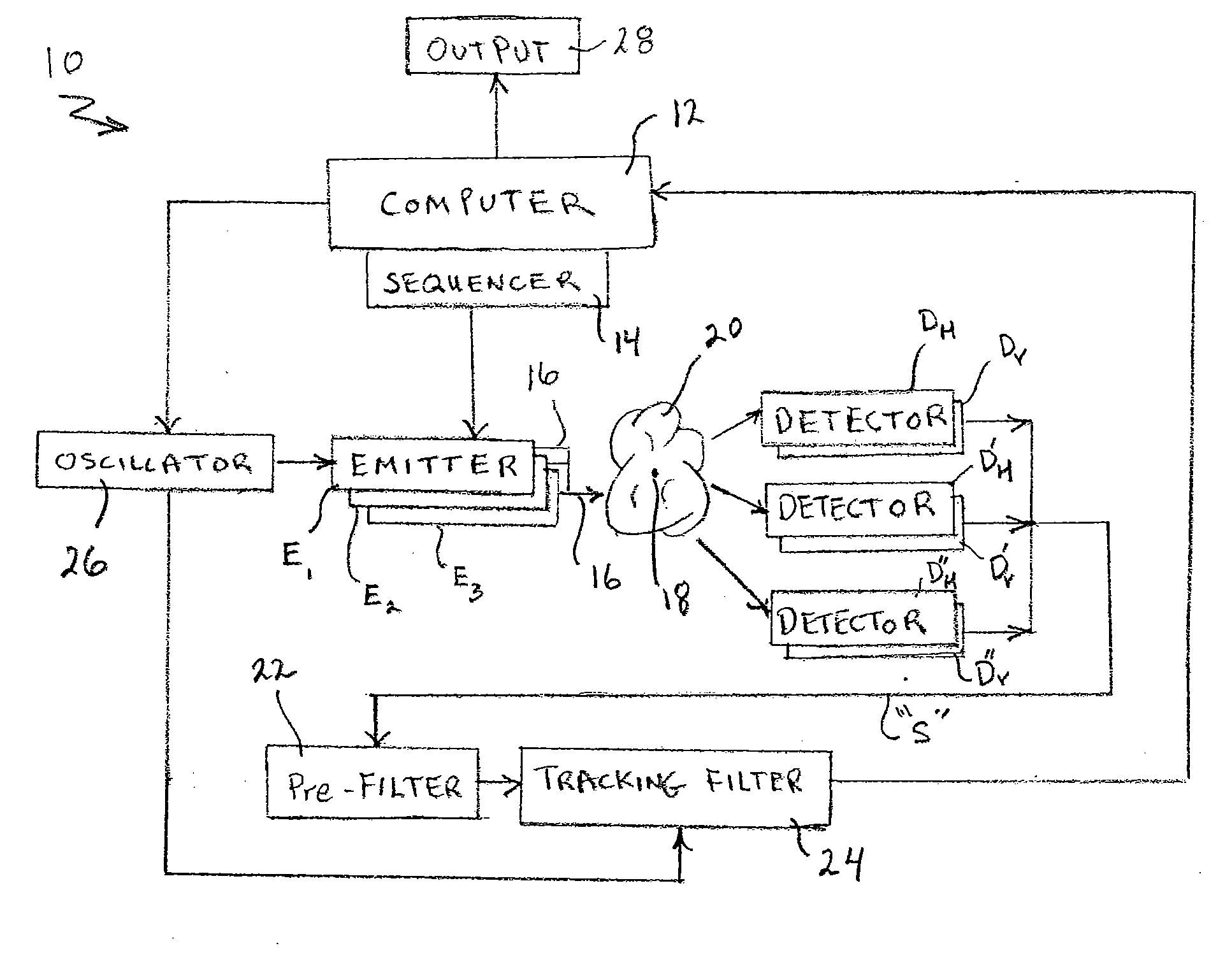
Figure 1 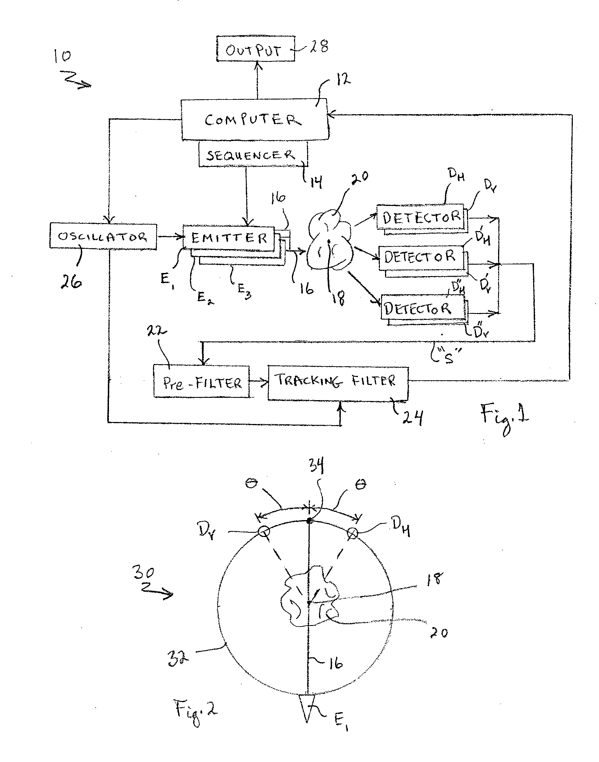
Figure 2 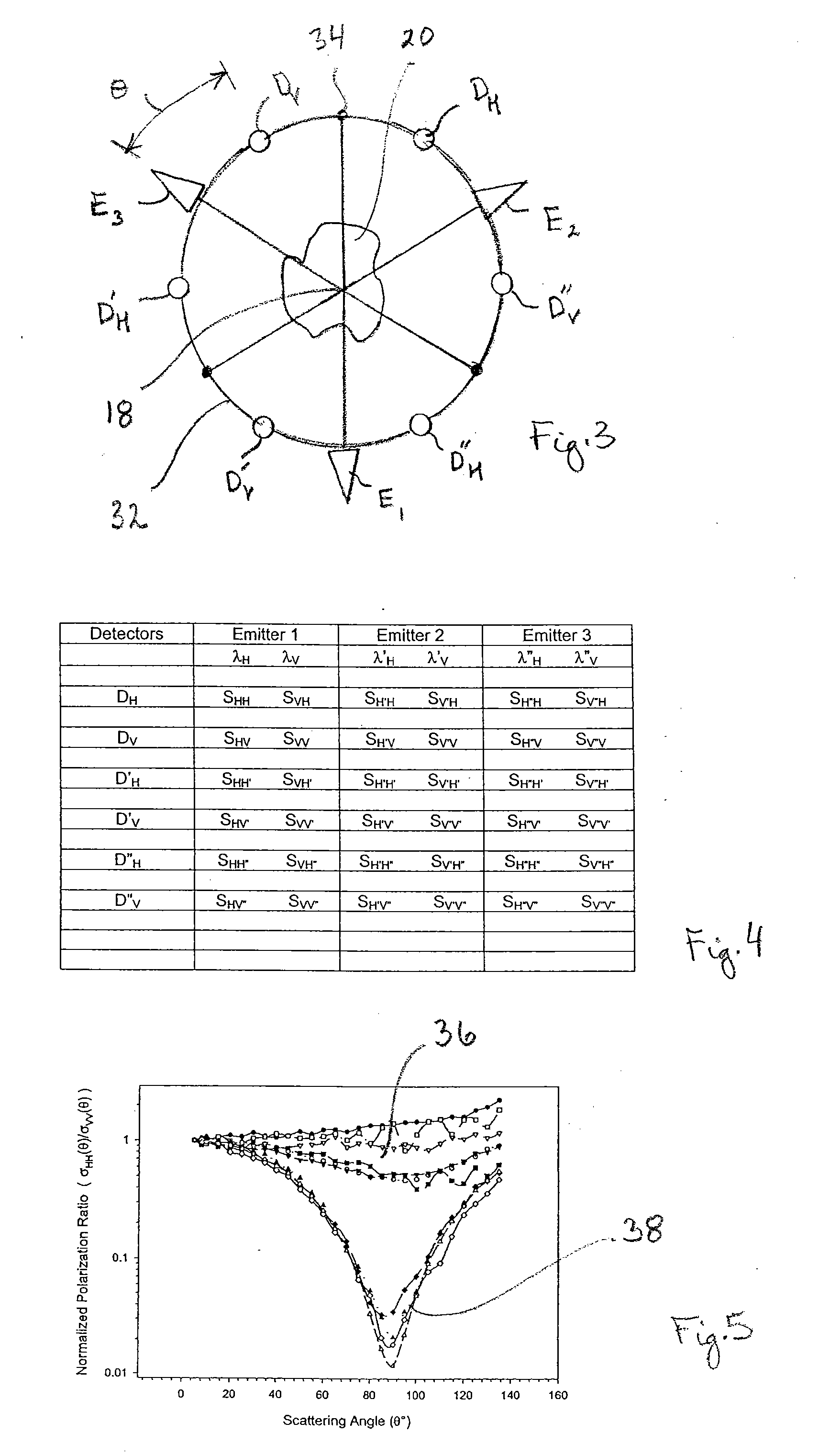
Figure 3
Abstract
Description
FIELD OF THE INVENTION
[0001] The present invention pertains generally to smoke analyzers. More particularly, the present invention pertains to optical devices that are used for smoke analyzers. The present invention is particularly, but not exclusively useful as an optical unit for generating signals to analyze smoke, wherein the signals are based on polarization, wavelength and scattering angle considerations.BACKGROUND OF THE INVENTION
[0002] Particles of different sizes and shapes (i.e. different materials) can become suspended in air for any of several different reasons. Tiny, condensed water droplets or ice crystals that become suspended in the atmosphere as clouds are a good example of this phenomenon. Clouds of particles, other than water, that may become suspended in air, such as dust and smoke, are also well known examples of the phenomenon. Unfortunately, smoke can be generated with many types of materials that will most likely cause undesirable consequences. In any event, an...
Examples
Embodiment Construction
[0017]Referring initially to FIG. 1, a system for an optical smoke detector in accordance with the present invention is shown and is generally designated 10. As shown the system 10 includes a computer 12 that is directly connected with a sequencer 14. In turn, the sequencer 14 is connected to a plurality of emitters, of which the emitters E1, E2 and E3 are exemplary. As intended for the system 10, each of the emitters E are positioned to direct a laser beam 16 to a point 18 in a smoke cloud 20. The light in the laser beam 16 will then be scattered as it passes through the smoke cloud 20, and will be received by a plurality of detectors, of which the detectors DH, DV, D′H, D′V, D″H, and D″V are exemplary. FIG. 1 also shows that these detectors (DH, DV, D′H, D′V, D″H, and D″V) are each connected, in sequence, to a pre-filter 22 and a tracking filter 24. Further, the system 10 is shown to include an oscillator 26 that is connected between the computer 12 and each of the emitters E1, E2...