
Tire handling system
Patent Information
- Authority / Receiving Office
- US · United States
- Current Assignee / Owner
- Publication Date
- 2016-11-17
- Estimated Expiration
- Not applicable · inactive patent
Smart Images
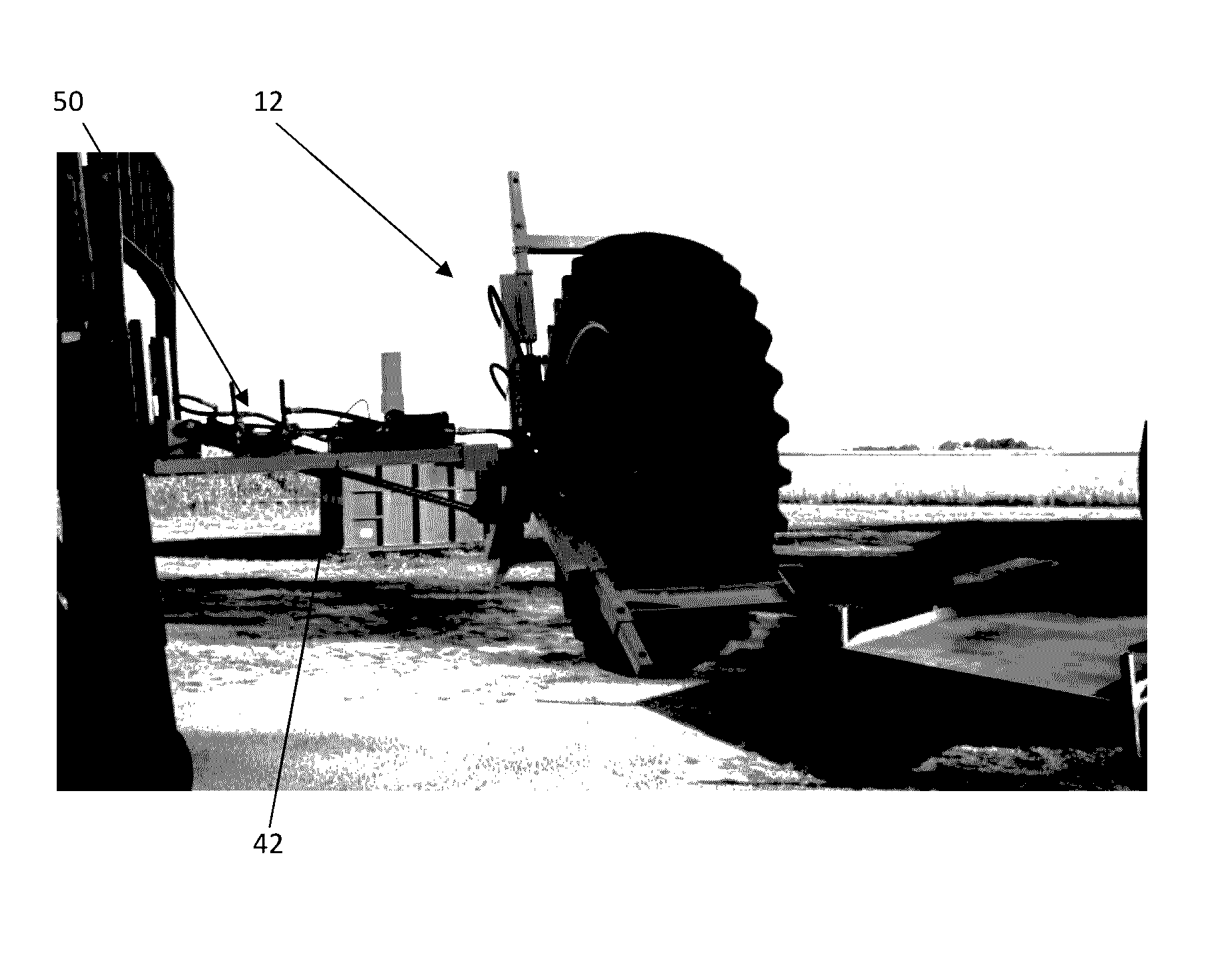
Figure 1 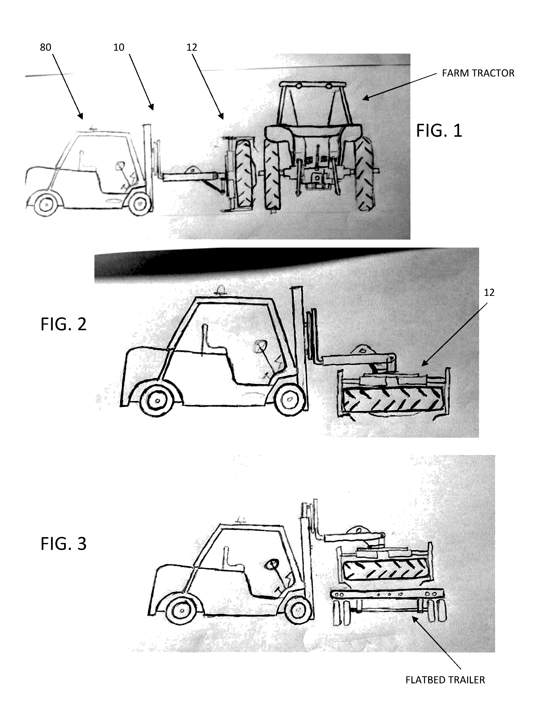
Figure 2 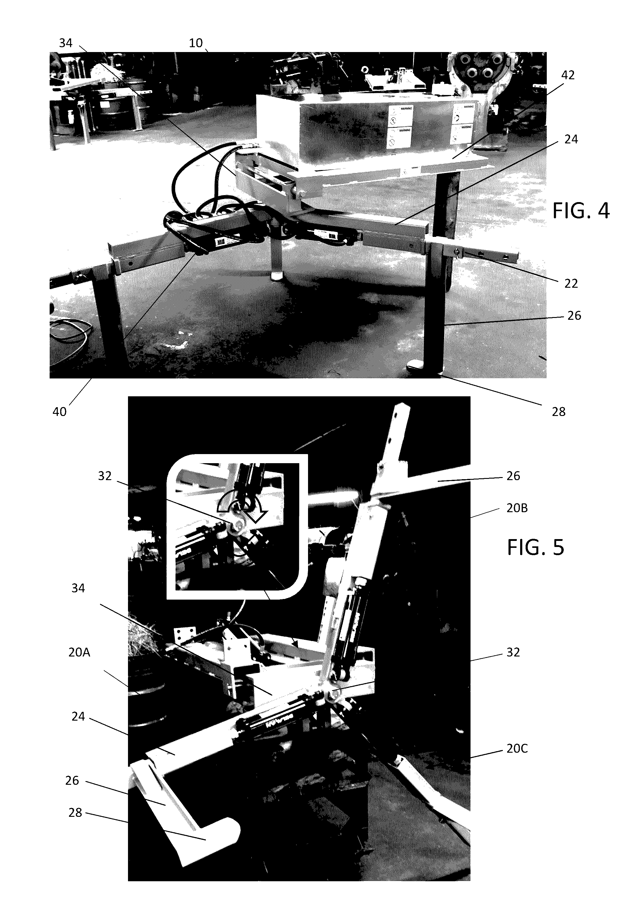
Figure 3
Abstract
Description
RELATED APPLICATION
[0001] The present application claims the filing benefit of U.S. Provisional Application No. 62 / 160,062, titled “Tire Handling System” and filed on May 12, 2015. The '062 Provisional Application is hereby incorporated by references.TECHNICAL FIELD OF THE INVENTION
[0002] The present application relates to a handling system for large tires, such as those used on semi-trucks, agriculture equipment, road construction machinery, and the like. Particularly, the application relates to a handling system for safely lifting and moving large tires from and onto such machinery.BACKGROUND OF THE INVENTION
[0003] Large tires used on trucks, heavy machinery and agriculture equipment, such as farm tractors and the like, can weigh from several hundred pounds to well-over a thousand pounds. Like much smaller tires, these treaded giants occasionally require removal for repair or replacement. However, for even two men, the task of removing, moving and replacing a tire on this type of hea...
Examples
Embodiment Construction
[0025]While this invention is susceptible of embodiments in many different forms, there is shown in the drawings and will herein be described in detail a preferred embodiment of the invention with the understanding that the present disclosure is to be considered as an exemplification of the principles of the invention and is not intended to limit the broad aspect of the invention to embodiments illustrated.
[0026]Referring now to FIGS. 1-14, there is illustrated an embodiment of a tire handling system generally referenced by the numeral 10. The following is a listing of components as described below and as labeled in the twelve appended drawing figures:[0027]12—Grapple;[0028]20—Arms for grapple (three arms (i.e., Ann A, Arm B and Arm C) used in illustrated embodiment);[0029]22—Adjustable portion of grapple arms;[0030]24—Stationary portion of the grapple arms;[0031]26—Engagement bracket;[0032]28—Flange;[0033]30—Central hub;[0034]32—Connector, allows arms to rotate approximately ±10 de...