
Injector nozzle coking compensation strategy
Patent Information
- Authority / Receiving Office
- US · United States
- Current Assignee / Owner
- Publication Date
- 2014-01-02
Smart Images
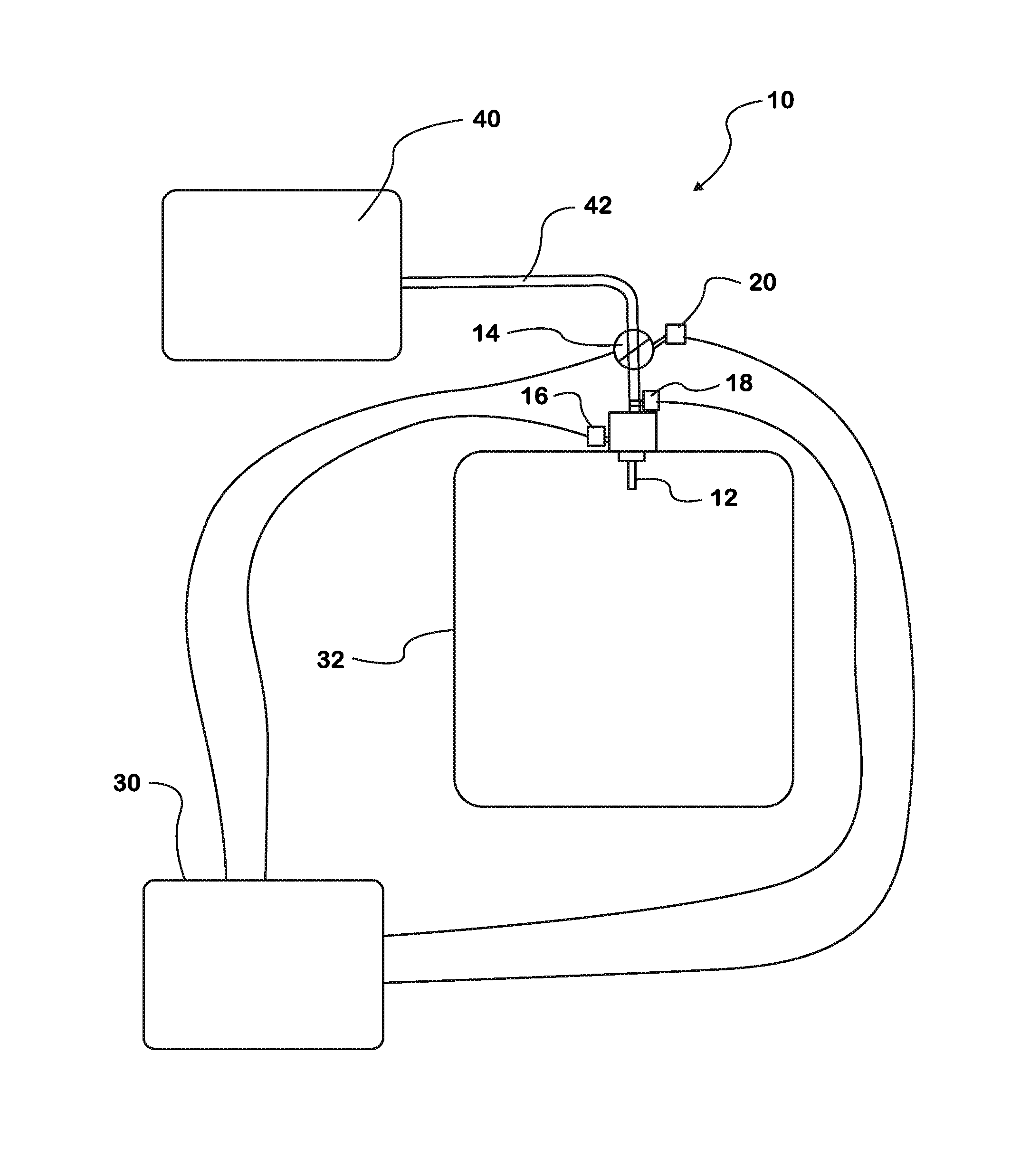
Figure 1 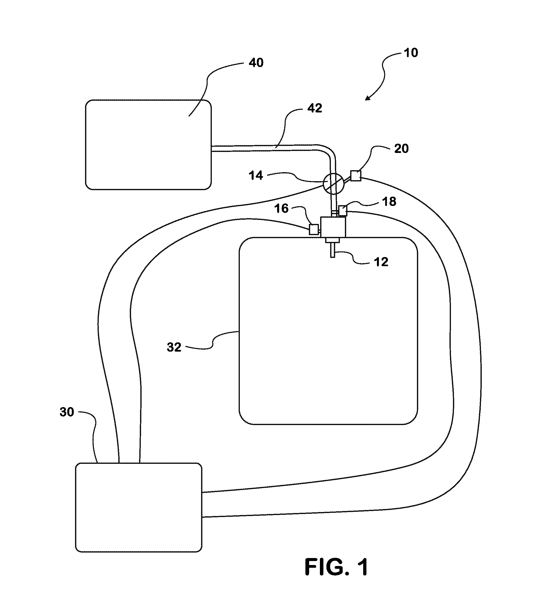
Figure 2 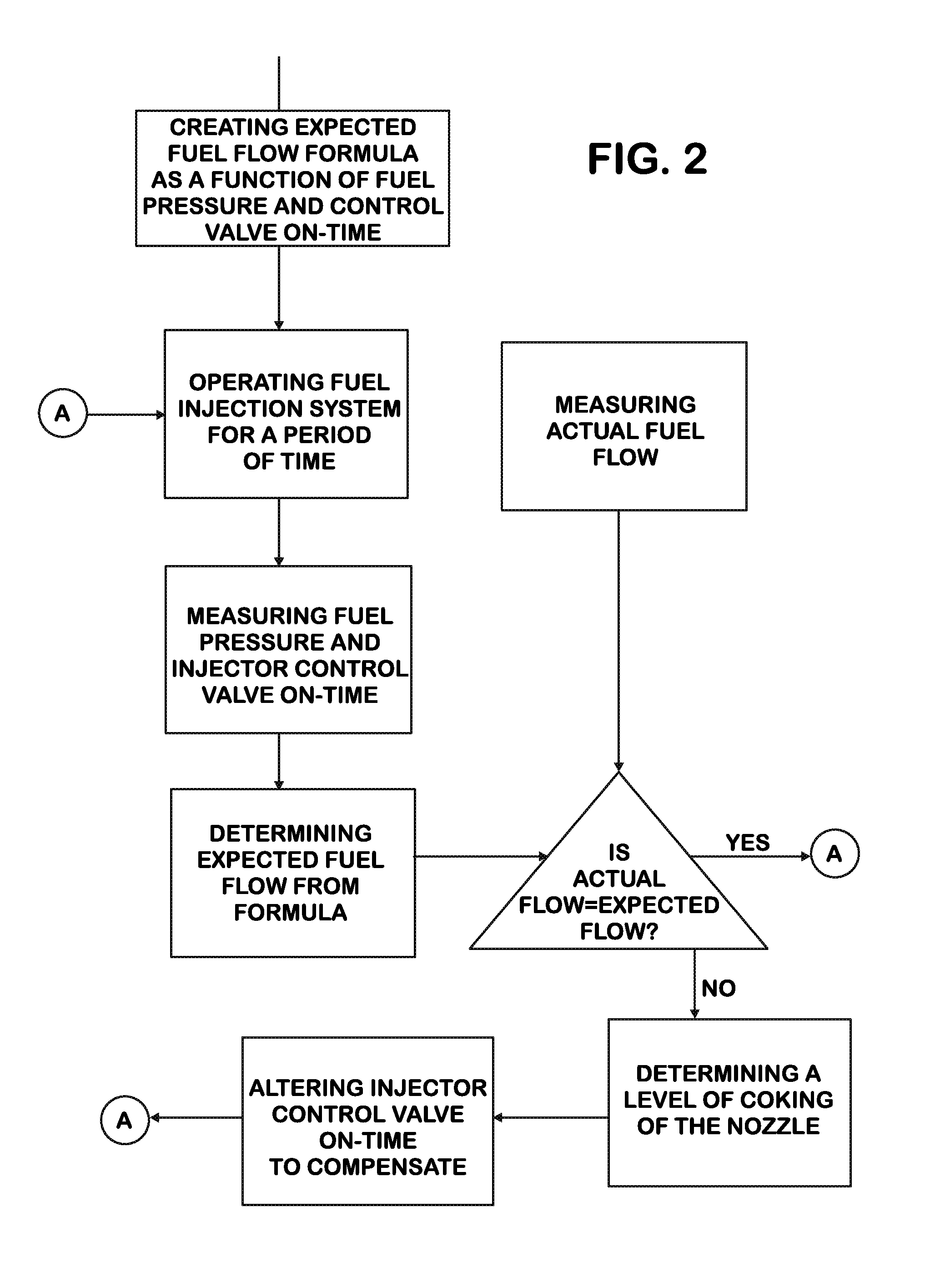
Figure 3
Abstract
Description
TECHNICAL FIELD OF THE INVENTION
[0001] The present device relates to a fuel-injection system using high-efficiency (HE) injection nozzles. Particularly, the present device relates to an a HE fuel-injection nozzle coking compensation strategy.BACKGROUND OF THE INVENTION
[0002] Fuel systems typically employ multiple closed-nozzle fuel injectors to inject high pressure fuel into the combustion chambers of an engine. Each of these fuel injectors includes a nozzle assembly having a cylindrical bore with a nozzle supply passageway and a nozzle outlet. The efficiency of the nozzle outlet or orifice is a measure of how effectively the energy stored in the fuel as pressure is converted into kinetic energy. The greater the kinetic energy, the more the fuel is broken apart (atomized), improving combustion completeness and lowering soot. High-efficiency (HE) nozzles, i.e., those with the highest orifice efficiency, are desirable for emissions.
[0003] Unfortunately, HE nozzles also have a greater pro...
Examples
Embodiment Construction
[0020]While this invention is susceptible of embodiments in many different forms, there is shown in the drawings and will herein be described in detail a preferred embodiment of the invention with the understanding that the present disclosure is to be considered as an exemplification of the principles of the invention and is not intended to limit the broad aspect of the invention to embodiments illustrated.
[0021]Referring to FIGS. 1-3, there is illustrated embodiments of both methods for creating an injector nozzle coking compensation strategy and a fuel injection nozzle system, generally designated by the numeral 10. The methods and systems are not limited to any particular type of injection nozzle, though high-efficiency nozzles are particularly useful.
[0022]Generally speaking, with reference to the drawing of FIG. 1, the fuel injection system 10 includes a fuel source 40, a fuel injection nozzle 12, a control valve 14, a fuel flow rate sensor 16, a pressure sensor 18, a control v...