
Subsea Valve, Flow System and Method of Use
Patent Information
- Authority / Receiving Office
- US · United States
- Current Assignee / Owner
- Publication Date
- 2017-10-26
- Estimated Expiration
- Not applicable · inactive patent
Smart Images
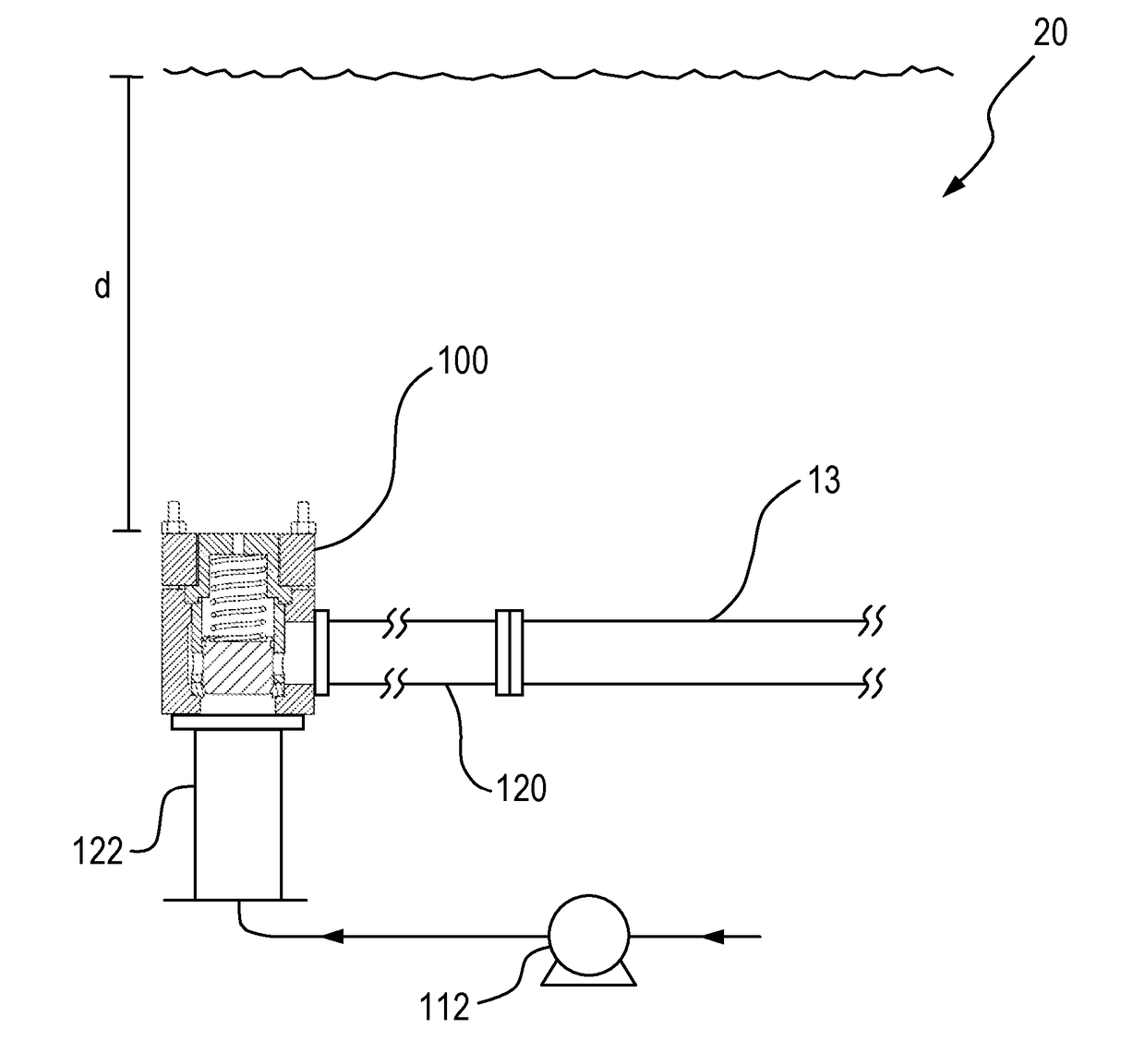
Figure 1 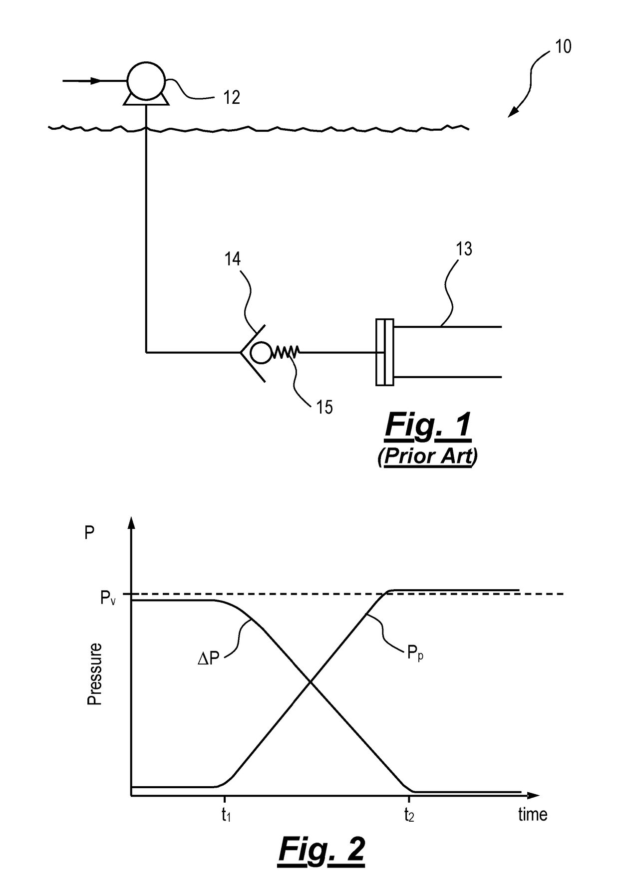
Figure 2 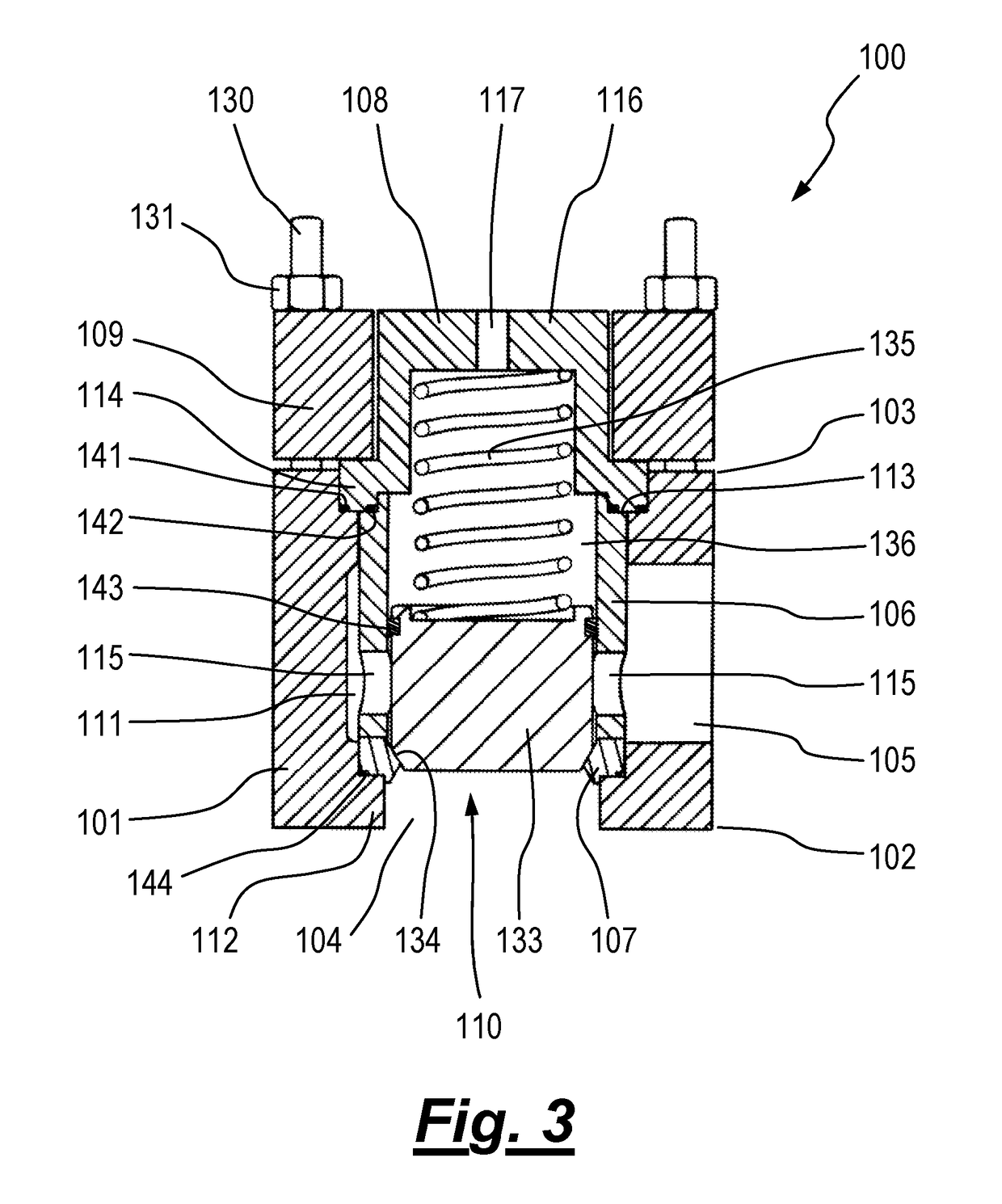
Figure 3
Abstract
Description
[0001] The present invention relates to a subsea valve, a flow system and a method of use, and in particular to subsea valve, a flow system and method of use in a pipeline filling, flooding or pigging application. Aspects of the invention relate to a subsea apparatus including a valve, a flow system including the subsea apparatus, and a method of use.BACKGROUND TO THE INVENTION
[0002] In the field of subsea engineering, it is common to lay pipelines on the seabed in a sealed condition and full of air or gas at atmospheric pressure. After the pipeline is laid, it may be flooded with seawater and may subsequently be pressure tested to ensure that there are no fluid leaks in the pipeline.
[0003] A number of subsea contractors provide systems which use combinations of hydrostatic pressure and / or a topsides or subsea booster pump for filling, flooding or pigging the pipeline, or increasing the pressure in the pipeline.
[0004] In shallow water applications, it is generally preferred to use a top...
Examples
Embodiment Construction
[0072]As noted above, FIG. 1 is a schematic representation of a flow system which is commonly used in the subsea industry in pipeline filling, flooding and pigging operations, and FIG. 2 is a graphical representation of pump pressure during use of the flow system in filling a pipeline. FIGS. 1 and 2 are useful for understanding the invention, an embodiment of which will now be described with reference to FIGS. 3 to 5.
[0073]The terms “upper”, “lower”, “above”, “below”, “up” and “down” may be used herein to indicate relative positions of the equipment. The invention also has applications in equipment used in orientations other than those shown in the drawings, and when these terms are applied to such orientations they may indicate “left”, “right” or other relative positions in the context of the orientation of the equipment.
[0074]Referring firstly to FIG. 3, there is shown a subsea valve generally depicted at 100, according to a first embodiment of the invention. FIG. 4 shows the valv...