
Blade driving device
a driving device and blade technology, applied in the direction of shutters, instruments, exposure control, etc., can solve the problems of large installation area, large actuator size, and inconvenient use, so as to reduce the thickness increase the size of the actuator, and facilitate the installation of the blade driving device.
Patent Information
- Authority / Receiving Office
- US · United States
- Patent Type
- Applications(United States)
- Current Assignee / Owner
- Publication Date
- 2018-02-08
Smart Images
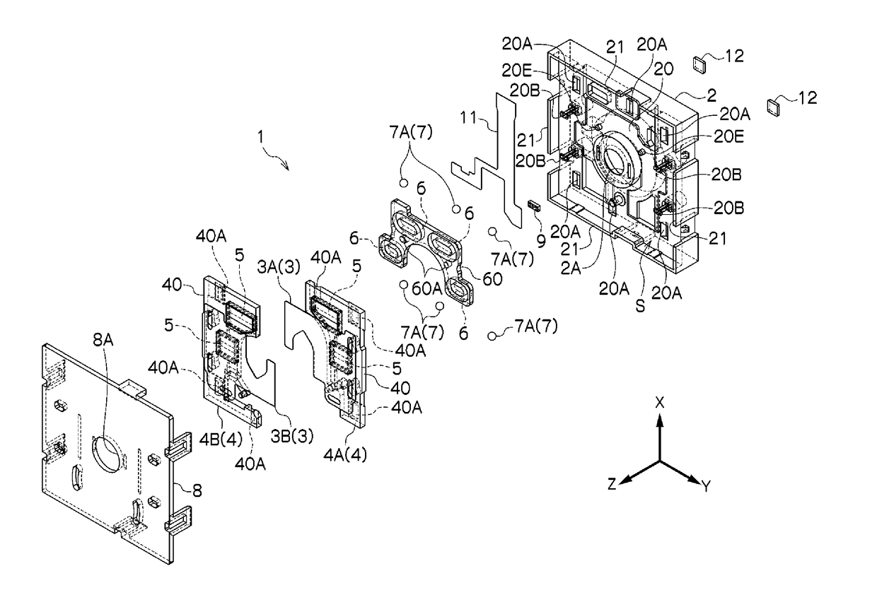
Figure 1 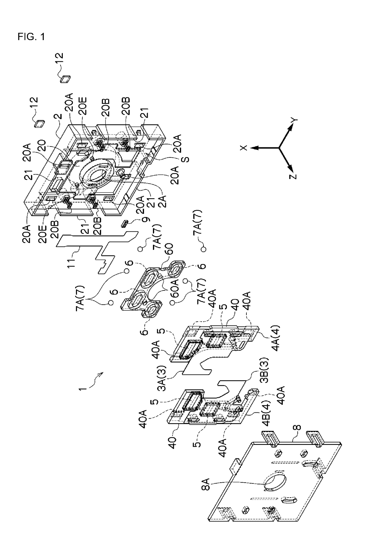
Figure 2 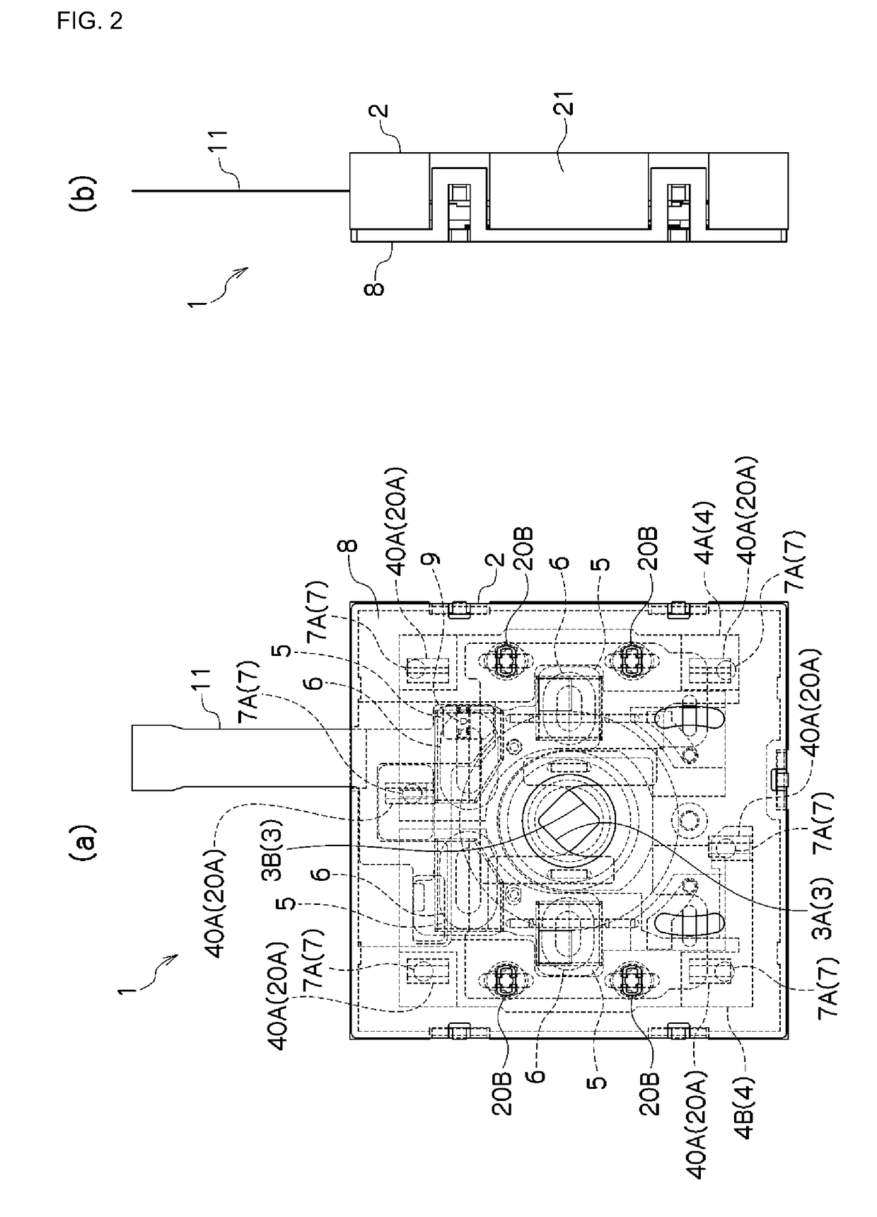
Figure 3
Abstract
Description
CROSS-REFERENCE TO RELATED APPLICATIONS
[0001] This is a U.S. national phase application under 35 U.S.C. §371 of International Patent Application No. PCT / JP2016 / 055766, filed Feb. 26, 2016, and claims benefit of priority to Japanese Patent Application No. 2015-039576, filed Feb. 27, 2015; Japanese Patent Application No. 2015-074383, filed Mar. 31, 2015; and Japanese Patent Application No. 2015-074384, filed Mar. 31, 2015; Japanese Patent Application No. 2015-074385, filed Mar. 31, 2015; Japanese Patent Application No. 2015-090750, filed Apr. 27, 2015; and Japanese Patent Application No. 2015-090752, filed Apr. 27, 2015; Japanese Patent Application No. 2015-102182, filed May 19, 2015; Japanese Patent Application No. 2015-128507, filed Jun. 26, 2015; Japanese Patent Application No. 2015-179912, filed Sep. 11, 2015; and Japanese Patent Application No. 2015-183797, filed Sep. 17, 2015. The entire contents of these applications are hereby incorporated by reference.FIELD OF TECHNOLOGY
[0002] ...
Examples
Embodiment Construction
[0083]Examples according to the present invention will be explained below in reference to the drawings. In the explanations below, identical reference symbols are assigned for identical positions in the different drawings, and redundant explanations are omitted. In the various drawings, the optical axial direction is defined as the Z direction, an axial direction within a plane that is perpendicular to the optical axis is defined as the X direction, and the direction that is perpendicular to the X direction within the plane that is perpendicular to the optical axis is defined as the Y direction. FIG. 1 is an exploded perspective diagram illustrating an example of a blade driving device according to an example according to the present invention, and FIG. 2 is a plan view and a side view of a blade driving device according to an example according to the present invention.
[0084]The blade driving device 1 comprises a base member 2, a blade member 3, and a driving member 4. The base memb...